Views: 0 Author: Site Editor Publish Time: 2026-09-16 Origin: Site
Increasing electrical loads and miniaturization in switching devices demand precise material selection to balance electrical conductivity with mechanical durability and corrosion resistance. Component failure due to improper contact material specification—such as micro-welding, excessive arc erosion, or mechanical fatigue—drives up warranty claims, necessitates frequent maintenance, and introduces severe safety risks. Evaluating and validating the exact composition, microstructural integrity, and surface finish of silver nickel alloys is essential for engineering reliable, long-lasting electrical contacts. You must match the material properties directly to the operational stresses of the switching device to prevent premature degradation under heavy loads. Proper specification guarantees consistent performance across millions of switching cycles and optimizes manufacturing processes for cold-headed rivets and stamped assemblies. We will break down how to validate these materials for field applications.
The specific Silver/Nickel (Ag/Ni) weight percentage ratio dictates the critical balance between electrical conductivity and arc erosion resistance.
Rigorous microstructural validation is required to ensure homogeneous nickel dispersion, which prevents localized failure in wire, strip, and sheet forms.
Transitioning from fine silver or cadmium-based contacts to silver nickel requires assessing tooling wear, fabrication constraints, and total lifecycle costs.
Standardized testing (e.g., % IACS, contact resistance stability) must align with the specific continuous and make/break load profiles of the application, comparing favorably against alternative composites like silver tin oxide or copper tungsten.
We must establish baseline requirements for continuous current carrying capacity versus peak make/break current loads. Switching devices experience vastly different stresses during steady-state operation compared to initial engagement. High-inrush events generate intense localized heat. You need to identify specific thermal management thresholds to prevent micro-welding when contacts close under heavy electrical loads.
To properly map the operational envelope, evaluate these specific parameters:
Continuous current rating and maximum allowable temperature rise at the terminal connections.
Peak inrush current duration, especially for capacitive loads or motor starting applications.
Mechanical impact forces, overtravel, and bounce duration during contact closure.
Environmental exposure, including ambient humidity, corrosive industrial gases, and extreme operating temperatures.
Mechanical bounce during closure exacerbates electrical arcing. Each bounce strikes a new arc, exponentially increasing thermal stress on the contact surface. Faster make/break speeds reduce arc duration but increase mechanical impact. Slower speeds reduce impact but prolong arc exposure. The contact material must accommodate these specific mechanical realities. Thermal dissipation capabilities directly influence the maximum allowable switching frequency. Inadequate thermal management leads to rapid material transfer and premature component failure.
Conventional fine silver boasts over 100% IACS conductivity. Despite this excellent electrical performance, it fails under high mechanical stress due to its low hardness and poor resistance to mechanical wear. It is highly susceptible to severe arc erosion during switching events. High temperatures easily melt fine silver, causing contacts to weld shut. You cannot rely on fine silver for medium or heavy-load applications because it lacks the structural integrity required for repeated arcing.
Introducing nickel into the silver matrix solves these inherent weaknesses. Silver and nickel are virtually immiscible in both liquid and solid states. They do not form solid solutions. Nickel acts as a discrete refractory phase distributed throughout the silver. This metallurgical structure enhances mechanical strength and arc resistance. Because nickel remains separate, it does not drastically degrade the silver's electrical conductivity. Utilizing engineered silver alloy materials provides the necessary durability. The nickel particles anchor the electrical arc, preventing deep localized melting. This dispersion strengthens the material against mechanical impact and reduces material transfer from the anode to the cathode.
You must contextualize silver nickel against other composite contact materials to avoid over-engineering or under-specifying the component. Different loads require entirely different metallurgical approaches.
Material Type | Primary Advantage | Primary Limitation | Ideal Application |
|---|---|---|---|
Silver Nickel (AgNi) | Stable contact resistance, excellent workability | Moderate anti-welding under extreme inrush | Medium-load relays, standard contactors |
Silver Tin Oxide (AgSnO2) | Superior anti-welding properties | Higher contact resistance, difficult to fabricate | High-inrush loads, automotive relays |
Copper Tungsten (CuW) | Extreme thermal shock resistance | Poor baseline conductivity, oxidation risk | High-voltage arcing, vacuum interrupters |
Silver Graphite (AgC) | Unmatched anti-welding characteristics | Rapid erosion under continuous mechanical wear | Circuit breakers (as a paired contact) |
Silver nickel occupies a highly practical middle ground. It delivers highly stable contact resistance over its lifespan and offers excellent workability for cold heading and stamping processes. You choose silver nickel for medium-load relays, contactors, and switches. It outperforms fine silver in durability and outperforms AgSnO2 in manufacturability. Understanding these comparative strengths prevents costly design errors.
Low-nickel concentrations range from 10 to 20 wt% Ni. You specify these grades for applications requiring high electrical conductivity and moderate mechanical wear. Domestic wall switches and light automotive relays utilize AgNi10 or AgNi15. These applications prioritize low temperature rise during continuous current flow. The lower nickel content ensures the contact resistance remains minimal while providing sufficient arc resistance for resistive or lightly inductive loads. Machining these lower-nickel grades is relatively straightforward, allowing for extended tool life during high-volume production.
High-nickel concentrations range from 30 to 40 wt% Ni. Heavy-duty switching devices demand these robust compositions. Industrial contactors, motor starters, and power relays require superior arc erosion resistance. AgNi30 and AgNi40 withstand severe arcing during high-current make/break cycles. The increased refractory phase prevents catastrophic welding under heavy inductive loads. However, you must accommodate the proportionally lower electrical conductivity in your thermal design, often requiring larger contact surface areas or heavier copper backing.
Ternary variants introduce additional elements for specialized performance. Wrought Copper Nickel Silver (Cu-Ni-Ag) grades offer unique advantages when applications demand superior corrosion resistance and enhanced mechanical strength exceeding 500 MPa. These ternary alloys maintain acceptable baseline conductivity while surviving harsh environments like marine or heavy industrial settings where binary alloys might tarnish or fail mechanically.
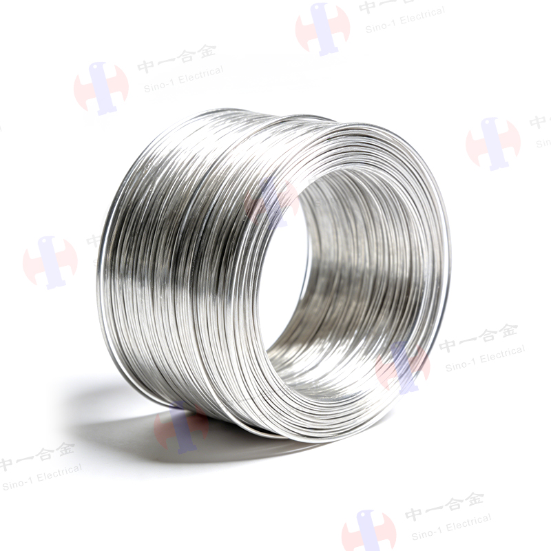
Manufacturing silver nickel contact wire involves strict drawing and annealing limitations. The material hardens rapidly during cold drawing. You must implement precise intermediate annealing cycles in controlled atmospheres to restore ductility and prevent wire fracture. Cold-headed contact rivets require a specific temper. If the wire is too hard, tungsten carbide heading dies wear out prematurely. If it is too soft, the rivet head may deform improperly, leading to inconsistent contact geometry. You must specify the exact grain size and tensile strength for automated riveting machines.
Certain engineering scenarios dictate different form factors. You may need to specify a silver alloy strip for stamped components. Complex contact profiles often require progressive die stamping. Strip materials allow for continuous, high-speed automated production. Multi-layer clad assemblies optimize material usage by cladding a thin layer of silver nickel onto a copper or brass carrier. This reduces precious metal consumption while maintaining performance at the critical contact point.
Heavy-duty switchgear often utilizes a silver alloy sheet. Large contact pads are punched or machined from these sheets. Sheet materials must exhibit uniform thickness and consistent mechanical properties across their entire surface. Internal stresses from rolling must be relieved through proper thermal treatment to prevent warping during subsequent machining or brazing operations. You must coordinate closely with metallurgical suppliers to define the optimal form factor and temper for your specific fabrication line.
You must establish strict criteria for evaluating nickel particle homogeneity. Silver nickel is typically manufactured via powder metallurgy. Atomization, blending, pressing, and sintering must distribute the nickel evenly throughout the silver matrix. Agglomerations of nickel create localized high-resistance spots, while silver-rich areas create weak points susceptible to deep arc erosion. You validate this dispersion using scanning electron microscopy (SEM). Metallographic cross-sections reveal the true internal structure of the contact material, ensuring the blending process was sufficient.
Grain size significantly impacts mechanical wear and electrical performance. Finer grain structures generally improve surface hardness. You should assess the impact of nanocrystalline silver alloy contact finishes. These advanced finishes offer superior wear rates compared to conventional silver. They extend component longevity by reducing material transfer during switching. The nanocrystalline structure provides more grain boundaries, which impede dislocation movement and increase the material's overall mechanical resilience under repetitive impact.
Define precise conductivity testing parameters across varying Ag/Ni ratios measured in % IACS (International Annealed Copper Standard). Accurate conductivity data is necessary for thermal management calculations. Millivolt drop tests across closed contacts verify real-world electrical resistance. These tests must be conducted under specified contact pressures using precision load banks and oscilloscope monitoring to ensure accurate, repeatable data.
Lifecycle testing validates contact resistance stability over time. You must subject the contacts to millions of switching cycles under actual load conditions. Monitor the temperature rise and resistance changes at regular intervals. Specify Vickers or Rockwell hardness testing for all incoming material lots. Tensile strength validation is required to ensure compatibility with automated fabrication equipment. Consistent mechanical properties prevent machine jams and reduce tooling wear on the factory floor.
Verify strict RoHS (Restriction of Hazardous Substances) compliance for all contact materials. Silver nickel serves as the primary substitute for silver cadmium oxide (AgCdO). Cadmium is heavily regulated and banned in most new electrical designs due to its toxicity. Silver nickel provides a safe, compliant alternative without sacrificing significant performance. You must maintain documentation proving the absence of restricted heavy metals in your supply chain.
Reference applicable ASTM and IEC standards governing electrical contacts. ASTM B693 outlines the standard specifications for silver-nickel electrical contact materials, detailing acceptable impurity levels and density requirements. IEC 60947 defines testing methodologies for low-voltage switchgear and controlgear. Adhering to these standards ensures your components meet global regulatory requirements and provides a common language for comparing different material suppliers.
You must map the inherent inverse relationship between conductivity and erosion resistance. Increasing the nickel content directly improves anti-welding properties. It hardens the material and reduces arc-induced material loss. However, this addition proportionally decreases overall electrical conductivity and increases the baseline contact resistance. You cannot maximize both properties simultaneously. You must identify the exact compromise required for your specific switching device.
Material Grade | Nickel Content (wt%) | Typical Conductivity (% IACS) | Hardness (HV) | Primary Application Focus |
|---|---|---|---|---|
AgNi10 | 10% | 75 - 85 | 60 - 80 | High conductivity, light relays |
AgNi20 | 20% | 65 - 75 | 70 - 90 | Balanced loads, automotive switches |
AgNi30 | 30% | 55 - 65 | 80 - 105 | Heavy-duty contactors, motor starters |
AgNi40 | 40% | 45 - 55 | 90 - 115 | High arc resistance, circuit breakers |
Thermal management becomes critical as nickel content increases. Lower conductivity generates more heat during continuous current flow. You must design adequate heat sinks or utilize heavier copper backing materials. Failure to manage this heat leads to thermal runaway and premature contact failure. The mechanical design of the switch must provide sufficient contact pressure. Higher pressure helps overcome the increased contact resistance inherent in high-nickel alloys and breaks through surface oxides.
Compare the initial raw material and processing costs against operational savings. High-purity silver alloys require complex powder metallurgy processes, including controlled atmosphere sintering and specialized extrusion. These manufacturing steps increase the upfront material price. However, the extended component lifespan offsets these initial expenses. Reduced maintenance intervals and lower warranty claims provide significant long-term value. A cheaper, lower-grade contact often costs more in replacement labor and brand damage.
Factor in the increased tooling wear associated with higher-nickel alloys. Harder materials degrade stamping dies and cold-heading tools faster. Machining costs rise when fabricating complex clad strip assemblies. You must budget for more frequent tool maintenance and replacement, often requiring upgrades to tungsten carbide tooling. Optimizing the temper and grain size of the incoming material helps mitigate this wear. Collaborating with your fabrication team ensures the chosen alloy balances performance with manufacturability.
Delamination presents a severe risk during the fabrication of clad materials. Extreme mechanical stress during cold heading can separate the silver alloy from its copper carrier. Cracking or material fatigue often occurs during aggressive stamping operations. These defects compromise both electrical performance and mechanical integrity. A cracked contact rivet will fail rapidly under operational arcing. You must identify these risks early in the prototyping phase.
Mitigation requires specifying precise annealing states before fabrication. Follow these steps to ensure structural integrity:
Define exact temper designations and grain size limits for all raw materials prior to ordering.
Conduct thorough bend tests and upset tests on incoming wire and strip lots to verify ductility.
Adjust tooling radii and clearance tolerances to accommodate the specific yield strength of silver nickel.
Apply proper lubrication during stamping and heading to reduce surface stress and prevent micro-cracking.
Batch-to-batch microstructural inconsistency poses a major supply chain risk. Variations in powder blending times, pressing pressures, or sintering temperatures alter the final material. Inconsistent nickel dispersion leads to unpredictable field performance. One batch may perform flawlessly, while the next suffers from rapid arc erosion. You cannot rely on visual inspection to detect these internal metallurgical flaws. Rigorous quality control protocols are mandatory.
Mandate strict Certificates of Analysis (CoA) for every material lot. The CoA must detail exact density measurements, chemical composition, and micrographic evidence of proper nickel dispersion. Implement routine incoming inspection protocols using SEM and hardness testing. Quarantine any lot that deviates from the approved metallurgical specifications. Building strong technical partnerships with reputable material suppliers ensures consistent quality and reliable traceability.
Request sample lots of specific Ag/Ni ratios to conduct application-specific lifecycle testing under actual load conditions.
Consult with metallurgical suppliers to optimize custom cladding, backing requirements, and temper designations for your specific tooling setup.
Evaluate nanocrystalline finishes during the prototyping phase to improve surface hardness and reduce material transfer.
Implement strict incoming quality control protocols, requiring Certificates of Analysis to verify homogeneous nickel dispersion before approving full production runs.
A: The maximum viable nickel content typically caps at 40 wt% for heavy-duty applications. Exceeding this limit severely degrades electrical conductivity and increases contact resistance. Higher nickel concentrations also make the wire excessively hard, rendering it unsuitable for standard cold-heading and riveting processes.
A: Silver nickel excels in medium-load applications, offering stable contact resistance and excellent workability. Silver tin oxide is preferred for high-inrush loads due to superior anti-welding properties but presents higher contact resistance and is significantly harder to fabricate and stamp.
A: Specify a ternary wrought copper nickel silver alloy when the application demands enhanced mechanical strength exceeding 500 MPa. It is also required when superior corrosion resistance is necessary, such as in marine or harsh industrial environments, while maintaining acceptable baseline electrical conductivity.
A: Direct replacement is rarely straightforward. While silver nickel improves mechanical durability and arc resistance, its lower conductivity and higher hardness require design adjustments. You must evaluate thermal management, increase contact pressure, and assess potential tooling wear before implementing it as a replacement.
A: Contact resistance increases due to surface oxidation, accumulation of carbonaceous deposits from arcing, and mechanical wear. Repeated make/break cycles under heavy electrical loads accelerate these degradation mechanisms. Proper alloy selection and adequate contact wiping action help mitigate this resistance buildup.
A: Microstructural dispersion is validated using scanning electron microscopy (SEM) and metallographic cross-section analysis. These advanced imaging methods ensure homogeneous nickel particle distribution. Consistent dispersion is critical for preventing localized high-resistance hot spots and uneven wear during operation.