Views: 0 Author: Site Editor Publish Time: 2026-09-14 Origin: Site
Undetected defects in high-reliability electrical components carry severe financial and operational consequences. When manufacturing flaws slip past initial production stages, the cost of scrap and rework multiplies exponentially upon final integration. The specific challenge lies in inspecting integrated components. Combining multiple discrete parts into single units inherently reduces overall manufacturing steps, but it introduces highly complex, multi-variable inspection requirements. Mechanical and electrical tolerances overlap tightly, meaning a slight dimensional deviation can immediately compromise conductivity or thermal management. To address these overlapping variables, manufacturers must adopt a structured evaluation framework for process inspection. Relying on reactive end-of-line testing is no longer sufficient. Production lines require proactive, inline quality assurance methodologies that leverage advanced optical sensors, high-speed electrical continuity checks, and machine learning defect analysis to isolate variances before they escalate into catastrophic failures.
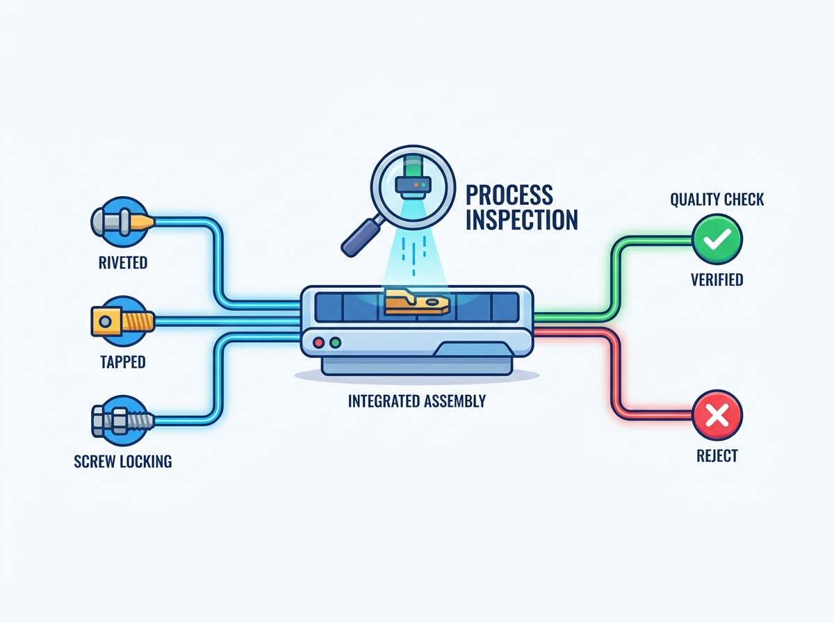
Inline vs. End-of-Line: Shifting to real-time, automated optical and electrical inspection reduces false acceptance rates and isolates variances at critical sub-assembly stage gates before final integration.
Assembly-Specific Criteria: Inspection protocols must be customized based on the fastening method (e.g., verifying shear strength for a riveted contact assembly vs. thread integrity for a tapped contact assembly).
AI and Sensor Integration: Deploying 2D/3D vision systems and machine learning algorithms drastically improves defect recognition, separating critical functional flaws from acceptable cosmetic anomalies.
Compliance as a Baseline: Adherence to AS9100D and ISO standards requires rigorous traceability, containment strategies, and documented Factory Acceptance Testing (FAT).
CapEx vs. Yield: Evaluating automated inspection systems requires modeling the upfront capital expenditure against the projected reduction in scrap rates and warranty claims.
Evaluating Integrated Electrical Contact Assemblies requires a multifaceted approach to quality control. The transition from discrete components to integrated units fundamentally alters the inspection landscape on the factory floor. You can no longer rely on simple visual checks when multiple materials and fastening methods merge into a single profile.
A successful inspection process hinges on zero critical defect pass-through, minimal false rejects, and cycle times that align perfectly with production throughput. When evaluating electrical contact assemblies, the baseline metrics must focus on functional reliability rather than purely cosmetic perfection. Inspection nodes must process parts in milliseconds. They utilize high-speed data acquisition to prevent bottlenecks. If the inspection cycle exceeds the manufacturing takt time, the entire production line stalls. Furthermore, the inspection system must demonstrate a high Process Capability Index (Cpk). We typically look for a Cpk greater than 1.33, proving that the measurement resolution is significantly finer than the allowable tolerance band of the component itself.
Consolidating multiple components into a single integrated unit streamlines manufacturing by eliminating redundant fastening phases. You remove secondary manual soldering or separate crimping operations. However, this consolidation means inspection nodes must be strategically positioned to validate these combined steps. Without precise inline monitoring, manufacturers lose visibility into individual component integrity. A single stamping or plating error hidden within a multi-part assembly becomes impossible to detect visually once the unit moves down the line. Strategic stage gates ensure that each sub-process is verified before the next layer of complexity is added. We deploy automated sensors at these gates to replace subjective human visual inspection entirely.
Inspecting these components involves a dual-nature verification process. Dimensional accuracy and electrical performance are inextricably linked. Mechanical checks must validate gap tolerances, coplanarity, and material thickness using laser profilometry or confocal sensors. Simultaneously, electrical verification requires testing contact resistance, dielectric strength, and overall conductivity. A contact might pass mechanical dimensional checks but fail electrical testing due to subsurface voids, micro-cracks in the plating material, or improper alloy distribution. Implementing 4-wire Kelvin resistance testing ensures that the measurement leads do not artificially inflate the resistance readings. Both mechanical and electrical parameters must be evaluated concurrently to guarantee field reliability.
Micro-deviations during the stamping, plating, or joining phases compound rapidly into severe operational hazards. A variation of a few microns in silver or gold plating thickness alters the thermal dissipation profile. This leads to overheating under high-current loads. Similarly, slight misalignment during the joining phase creates uneven pressure distribution across the contact interface. This uneven distribution accelerates mechanical wear, increases constriction resistance, and elevates the risk of micro-arcing during switching operations. These micro-deviations ultimately manifest as macro-failures in the final integrated unit. They cause catastrophic system shutdowns, thermal runaway, or complete electrical continuity loss in industrial applications.
High-resolution 2D and 3D vision systems, combined with laser displacement sensors, form the backbone of real-time dimensional verification. These automated measurement sensors capture topographical data at micron-level accuracy without interrupting line speed. Utilizing telecentric lenses eliminates parallax errors. This ensures precise edge detection on complex stamped components regardless of their position in the field of view. By deploying structured light projection and chromatic confocal sensors, manufacturers generate dense point clouds to map the surface geometry of complex profiles. This allows the system to instantly identify burrs, scratches, or dimensional shifts that exceed specified tolerances.
Integrating machine learning algorithms transforms raw optical data into actionable intelligence. AI-driven systems continuously analyze defect patterns, improving their detection accuracy over time through supervised and unsupervised learning models. Unlike traditional rule-based vision systems that struggle with varying lighting conditions, oil residues, or minor surface reflections, neural networks differentiate between functional flaws and acceptable cosmetic anomalies. This adaptive capability allows the inspection system to recognize new variance patterns. It dynamically adjusts its parameters to maintain high yield rates without compromising quality. Edge computing architectures deploy these AI models directly at the inspection station, enabling microsecond decision-making without latency.
Setting up an effective AI inspection node requires specific steps:
Capture a baseline dataset of at least 500 known good parts under standard production lighting.
Introduce a controlled sample of 50 to 100 parts with known, measured defects (e.g., specific scratch depths, missing plating).
Train the neural network to isolate the functional defects from acceptable background noise like stamping oil residue.
Deploy the model to the edge device and run a shadow mode test alongside traditional inspection to validate accuracy.
Activate automated rejection logic once the AI model achieves a false reject rate below the target threshold.
Integrating continuity, resistance, and high-potential (hipot) testing directly into the assembly workflow validates electrical integrity. Automated test probes, such as spring-loaded pogo pin fixtures, interface with the components at high speeds. They inject specified currents to measure voltage drop and calculate precise micro-ohm resistance. Hipot testing applies elevated voltages to ensure insulation materials and dielectric gaps withstand transient electrical spikes without breaking down or allowing arc-overs. These inline checks verify that the conductive paths remain uncompromised after severe mechanical deformation processes like riveting, staking, or crimping. We monitor pogo pin wear closely, as degraded test probes will generate false resistance readings.
A robust quality assurance strategy balances 100% inline Non-Destructive Testing (NDT) with batch-sampled destructive testing. NDT methods, such as optical scanning, ultrasonic testing, and eddy current evaluation, verify every unit on the line without altering its physical state. Destructive testing remains necessary for deep structural validation. Cross-sectioning involves potting the assembly in resin, grinding, polishing, and etching the surface to examine intermetallic layer formation under a metallurgical microscope. Mechanical pull tests and shear tests provide empirical data on joint integrity. The strategic deployment of both methodologies ensures comprehensive defect coverage from the surface down to the atomic bonding level.
Factory Acceptance Testing (FAT) and Site Acceptance Testing (SAT) are mandatory protocols for validating inspection equipment before full-scale production launch. FAT occurs at the equipment manufacturer's facility. It verifies that the sensors, PLC logic, and software meet the baseline technical specifications using master sample parts. This phase includes rigorous gauge capability studies and dry runs. SAT takes place on the actual production floor. It ensures the equipment integrates seamlessly with the specific environmental conditions, material handling conveyors, and ambient lighting of the facility. SAT culminates in a continuous run test to validate the system's uptime and false reject rates under real-world manufacturing stresses.
When evaluating a riveted contact assembly, inspectors must target specific mechanical failure modes such as over-staking, under-staking, and radial cracking around the rivet head. Over-staking causes excessive material deformation, potentially fracturing the brittle contact substrate. Under-staking leaves the mechanical joint loose, leading to high electrical resistance, fretting corrosion, and eventual thermal runaway. Inspection techniques utilize 3D profilometry and laser triangulation to measure rivet head height and diameter post-deformation. Inline resistance testing across the cold-headed boundary verifies that the mechanical joint provides an optimal conductive path without internal voids or oxidized interfaces.
The structural integrity of a tapped contact assembly relies entirely on precise internal thread geometry. Critical failure modes include cross-threading, insufficient thread depth, thread galling, and internal burr formation. Automated thread verification methods replace slow, manual go/no-go gauges with high-speed eddy current probes or vision-based internal thread mapping. During the tapping process itself, torque-to-yield monitoring tracks the rotational force applied by the servo-driven spindle. Sudden spikes or drops in torque immediately flag a broken tap, material hardness variations, or stripped threads. This allows the system to eject the non-conforming part before it reaches the next assembly station.
Validating a screw locking contact assembly requires strict oversight of fastening dynamics and mechanical retention. Inadequate seating torque, vibration-induced loosening, and thread stripping are the primary failure modes that compromise the electrical connection. Inline torque monitoring systems capture the exact tightening curve for every fastener, ensuring it falls within the specified tolerance window. Optical verification systems confirm the seating depth of the fastener head. They detect cross-threaded or partially driven screws that torque monitors might miss due to friction anomalies. Batch-sampled mechanical pull-out strength validation ensures the threaded joint withstands the required axial loads without yielding.
Inspection Methodologies by Assembly Type
Assembly Type | Primary Failure Modes | Inline Inspection Technology | Verification Metric |
|---|---|---|---|
Riveted Contacts | Over-staking, under-staking, radial cracking, loose joints. | 3D Profilometry, Laser Triangulation, Micro-ohm Meters. | Rivet head height/diameter, joint shear strength, contact resistance. |
Tapped Contacts | Cross-threading, insufficient depth, internal burrs, galling. | Eddy Current Probes, Spindle Torque Monitoring. | Thread pitch integrity, tapping torque curve, go/no-go automation. |
Screw Locking Contacts | Inadequate seating torque, vibration loosening, stripped threads. | Inline Torque Transducers, Optical Depth Verification. | Torque vs. angle curve, fastener seating depth, pull-out strength. |
Aligning inspection process outputs with AS9100D and ISO 9001 requirements demands strict adherence to documented tolerance verification. These aerospace and industrial quality management systems mandate that every inspection node produces verifiable, immutable data. Measurement system analysis (MSA) and gauge repeatability and reproducibility (GR&R) studies must be conducted regularly. They prove that the inspection equipment consistently measures within the required confidence intervals. Equipment calibration records must be integrated directly into the quality management software to prevent operators from running production on uncalibrated sensors. We laser mark 2D matrix codes on components to ensure every measurement ties back to a specific physical part.
Automated logic is required to immediately isolate non-conforming parts. When a vision system or torque monitor detects a failure, the programmable logic controller (PLC) must trigger a physical rejection mechanism. We use high-speed pneumatic blow-offs or diverter gates to route the defective unit into a locked quarantine bin. This physical separation prevents any possibility of the part re-entering the production stream. Simultaneously, the system logs the exact failure parameter. It initiates root-cause analysis protocols to determine if the defect originated from raw material variance, tool wear, or machine misalignment.
Complete lifecycle traceability requires tying inspection data directly to individual part serial numbers or batch codes. Optical measurements, torque values, and electrical continuity loop checks are aggregated into a centralized database. This documentation ensures that if a field failure occurs, engineers retrieve the exact manufacturing and inspection history of the specific unit, down to the exact torque applied to a single screw. Loop checks verify that the analog or digital data transmitted from the sensor matches the data recorded in the database. This eliminates communication errors and ensures data integrity across the network.
Implementing inline inspection requires balancing the depth of analysis against the required throughput of the manufacturing line. High-resolution 3D tomographic scanning provides unparalleled internal visibility, detecting microscopic subsurface voids. However, it operates at a fraction of the speed of standard 2D optical inspection. Manufacturers must determine the defect size threshold that impacts functionality. You select a sensor resolution that captures those defects without bottlenecking the cycle time. Often, a hybrid approach works best. We deploy high-speed 2D cameras for 100% surface inspection and reserve slower 3D scanning for batch sampling or offline auditing.
Dedicated, custom-built inspection fixtures offer maximum stability and precision for high-volume, low-mix production runs. They lock the component into a highly repeatable position, minimizing measurement noise. However, they lack the agility to accommodate design changes. Conversely, programmable robotic vision systems mounted on multi-axis arms provide immense flexibility. They adapt easily to multiple assembly variants through simple software recipe changes. The trade-off lies in the initial programming complexity and slightly longer cycle times required for the robot to maneuver into various inspection poses. Facilities managing high-mix production environments heavily favor flexible robotic architectures to minimize tooling changeover downtime.
Measurement sensors inherently lose accuracy over time due to thermal fluctuations, mechanical vibration, and component aging. This calibration drift poses a severe risk to quality assurance, potentially allowing out-of-tolerance parts to pass. To mitigate this, facilities establish protocols for automated calibration verification. Utilizing certified master parts with known, traceable dimensions, the inspection system runs a verification cycle at the start of every shift. If the sensor readings deviate from the master part baseline by a predefined margin, the system automatically halts production. It alerts maintenance personnel until recalibration is performed.
Overly tight inspection parameters inevitably lead to high false reject rates. Perfectly functional parts are discarded due to minor cosmetic anomalies like water spots or slight plating discoloration. This operational inefficiency drains resources and artificially inflates scrap metrics. Optimizing AI-driven algorithms manages Type I errors effectively. By training neural networks on extensive datasets of both acceptable variations and functional defects, the system learns to differentiate accurately. This continuous learning drastically reduces false rejects while maintaining strict quality standards. It ensures that only genuinely defective components are quarantined.
Integrating new inspection hardware with legacy Manufacturing Execution Systems (MES) or Enterprise Resource Planning (ERP) software often creates technical bottlenecks and data silos. Modern inspection equipment generates massive volumes of high-frequency data that older MES architectures cannot process in real-time. Successful integration requires edge computing gateways that aggregate, filter, and format the sensor data locally. These gateways transmit only the pass/fail metrics and statistical process control (SPC) trends to the central MES. This ensures seamless data flow across the facility without overloading the network bandwidth.
Audit current end-of-line defect rates to identify the primary failure modes escaping detection.
Map identified defects back to their originating sub-assembly processes on the production floor.
Deploy targeted inline optical or electrical sensors at those specific high-risk stage gates.
Update containment workflows to automatically isolate non-conforming units into locked quarantine bins.
Establish a daily calibration verification routine using certified master parts to prevent sensor drift.
A: Inspecting discrete contacts focuses solely on single-part dimensional and material properties. Integrated assemblies require complex, multi-variable inspection where mechanical tolerances and electrical performance overlap. The inspection must validate the interaction between joined components, ensuring that fastening processes like riveting or welding do not compromise the overall conductive path or thermal dynamics.
A: Automated optical inspection utilizes high-resolution 3D profilometry to instantly measure rivet head height, diameter, and deformation geometry. By detecting micro-cracks, over-staking, or under-staking in real-time, the system ejects defective units immediately. This prevents faulty sub-assemblies from progressing down the line, reducing final scrap rates and significantly improving overall production yield.
A: Traditional rule-based vision systems often flag functional parts as defective due to minor lighting changes or harmless cosmetic marks. AI-driven algorithms utilize neural networks trained on vast datasets to distinguish between critical structural flaws and acceptable surface anomalies. This adaptive learning drastically lowers false reject rates while maintaining strict functional quality standards.
A: High-speed inline verification utilizes eddy current probes or automated vision-based thread mapping instead of manual go/no-go gauges. Additionally, torque-to-yield monitoring on the tapping spindle tracks rotational force in real-time. Any deviation in torque instantly identifies stripped threads or broken taps, ensuring 100% verification without impacting the manufacturing cycle time.
A: Vibration resistance is validated through a combination of inline torque monitoring and batch-sampled mechanical testing. Automated drivers record the exact seating torque of every fastener to ensure it meets engineering specifications. Subsequently, sample units undergo accelerated mechanical shock and vibration profiling to verify that the threaded joints do not loosen under operational stress.
A: AS9100D establishes stringent aerospace-level quality management protocols. It mandates rigorous traceability, immutable inspection data logging, and strict containment workflows for non-conforming parts. Adhering to this standard ensures that inspection equipment is regularly calibrated, measurement systems are validated through GR&R studies, and all quality control processes are thoroughly documented and repeatable.