Views: 0 Author: Site Editor Publish Time: 2026-09-16 Origin: Site
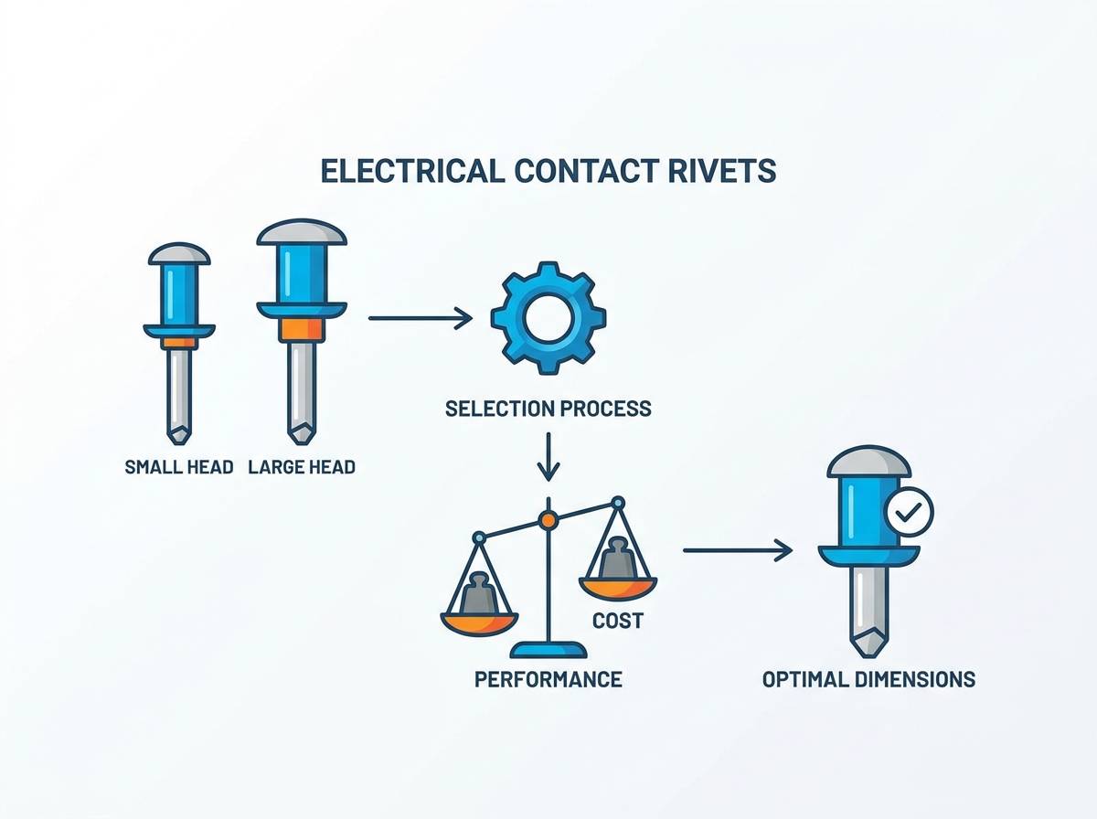
Precision in head dimensions dictates the lifecycle, thermal stability, and reliability of electromechanical switches. Undersized contact heads cause rapid overheating, severe arc erosion, and catastrophic failure under load. Oversized heads waste expensive precious metals and create spatial interference inside compact switchgear housings. You need a strict technical framework to evaluate and select exact head dimensions. This means calculating the ideal diameter, height, shape, bearing surface, and head-to-shank ratios based on real-world electrical loads. By applying these dimensional parameters, you balance electrical performance demands with practical manufacturing limits. This ensures your components operate flawlessly over hundreds of thousands of cycles without micro-welding or structural degradation.
Current-to-Diameter Correlation: Head diameter must be strictly scaled to the continuous current rating, anticipated arc erosion, and the required bearing surface of the application.
The Head-to-Shank Ratio: Mechanical stability during the riveting process relies on a precise head-to-shank (body) diameter ratio; exceeding structural limits causes deformation.
Material-Driven Sizing: The choice between solid alloys, a silver button contact, or a powder metallurgy contact dictates minimum head thickness and thermal mass requirements.
Shape Dictates Function: Head configurations (flat, domed, spherical, protruding) fundamentally alter the mating surface area, contact resistance, and mechanical wear patterns.
Defining a successful dimension specification requires looking beyond simple mechanical fit. A properly sized component must maintain electrical resistance below a specific milliohm threshold over an extended lifecycle. It must also ensure a secure mechanical fastening to the terminal arm without loosening under continuous vibration or thermal cycling. Designing reliable Electrical Contacts involves treating the head dimensions as active components in the electrical circuit.
We measure success through specific operational metrics on the test bench and in the field. You must hit these targets to validate your dimensional choices:
Maintaining a stable voltage drop across the closed switch under full continuous load.
Preventing the mating surfaces from exceeding the maximum allowable temperature rise during operation.
Surviving the target number of make-and-break cycles without exposing the base metal.
Holding the mechanical riveting force without deforming the terminal arm or cracking the contact head.
The physical volume of the head directly dictates its ability to manage heat. You calculate this volume using the standard cylinder formula. This volume represents the thermal mass available to absorb and dissipate heat generated by electrical resistance during operation. When current flows through the mating surfaces, localized resistance generates Joule heating. A larger thermal mass acts as an immediate heat sink. It pulls thermal energy away from the mating interface and distributes it into the terminal arm.
You calculate the thermal mass by determining the volume of the head geometry. For a standard cylindrical flat head, you multiply the surface area by the height. You factor in the specific heat capacity of the chosen alloy. Silver absorbs heat differently than a silver-tin-oxide blend. When the switch closes, the initial contact resistance generates immediate heat. If the head volume is too small, the temperature gradient spikes. The heat cannot transfer into the terminal arm fast enough. The mating surface exceeds the softening point of the alloy. The material deforms under the mechanical pressure of the contact springs. This deformation increases the contact area but destroys the designed geometry, leading to sluggish opening times and eventual failure.
If you specify a head with insufficient mass, the component loses its ability to dissipate heat rapidly. During high-inrush current events, the temperature at the mating surface spikes dramatically. Without adequate volume to absorb this energy, the metal reaches its melting point almost instantly. This localized melting causes micro-welding. The two mating surfaces fuse together, preventing the switch from opening and leading to immediate device failure.
Thermal Mass and Current Rating Guidelines
Continuous Current Rating | Minimum Recommended Head Diameter | Minimum Thermal Mass Requirement | Primary Heat Dissipation Path |
|---|---|---|---|
Low (0.1A - 5A) | 1.5mm - 3.0mm | Low volume; surface radiation sufficient | Directly through the mating surface |
Medium (5A - 20A) | 3.0mm - 5.0mm | Moderate volume; requires solid shank transfer | Through the shank into the terminal arm |
High (20A - 50A+) | 5.0mm - 8.0mm+ | High volume; requires thick head and backing plate | Through the terminal arm and external heat sinks |
Every time an electromechanical switch opens under load, it draws an electrical arc. This plasma arc generates extreme temperatures that vaporize a microscopic amount of the contact material. Over thousands of cycles, this material loss alters the physical geometry of the component. The head height serves as the primary sacrificial layer to accommodate this inevitable arc erosion.
The type of electrical load dictates the severity of the arc and the required head height. Resistive loads, like heating elements, produce predictable arcs that extinguish quickly. You specify a standard erosion allowance for these applications. Inductive loads, such as electric motors and heavy transformers, store energy in magnetic fields. When the switch opens, this stored energy discharges across the opening gap, sustaining the plasma arc for a significantly longer duration. This sustained arc vaporizes a larger volume of metal per cycle. You must increase the head height by 20% to 40% to compensate for inductive kickback. Capacitive loads draw massive inrush currents upon closing. This causes micro-arcing before the contacts fully seat. You specify a larger head diameter to handle the initial current density and prevent the surfaces from welding shut during the bounce phase.
You calculate the expected material loss per 10,000 cycles to establish a baseline height requirement. If the application involves high inductive loads, the arc duration increases. This demands a thicker sacrificial layer. You evaluate the load characteristics, determine the total required operations, and specify a head height that ensures enough precious metal remains at the end of the device's intended lifespan.
Specifying dimensions requires breaking down the physical geometry into individual variables. You calculate these variables sequentially during the design phase. You start from the base terminal requirements and work outward to the mating surface.
The body diameter serves as the baseline metric for all other dimensions. The terminal hole size dictates this shank diameter. Once you establish the shank size, you determine the head diameter by balancing electrical mating requirements with mechanical fastening rules. A standard engineering rule dictates that the rivet's body diameter should be at least three times the thickness of the thickest sheet being joined. Consequently, the head diameter must be sufficiently larger than the body diameter to provide a substantial bearing surface.
This bearing surface prevents the electrical contact rivets from pulling through the terminal arm under mechanical stress. You also evaluate the relationship between the head diameter and the overall footprint of the switch mechanism. If you specify a diameter that is too large, you risk spatial interference with adjacent components. The final diameter provides enough surface area to keep current density low while fitting safely within the mechanical envelope.
You differentiate between the total head height and the usable electrical thickness. In solid rivets, the entire head consists of the contact alloy. In bi-metal or clad designs, only the top layer provides the necessary electrical properties. The lower portion consists of a highly conductive base metal like copper. You ensure the usable thickness of the precious metal layer meets the arc erosion requirements.
Thicker heads provide a longer operational life by offering more sacrificial material. Adding height increases the kinetic mass of the moving contact arm. Higher mass slows down the switching speed and increases the kinetic energy upon impact. This exacerbates contact bounce. Excessive bounce causes secondary arcing, which rapidly accelerates erosion. You optimize the height to provide sufficient life without inducing harmful mechanical bounce.
Mechanical stability during the manufacturing process relies heavily on the head-to-shank diameter ratio. Cold heading and riveting processes apply immense compressive force to deform the shank and secure the assembly. Engineering standards cap the maximum head diameter at specific multiples of the shank diameter based on material ductility.
The cold heading process forces wire stock into a die to form the head. The material flows outward under extreme pressure. Every alloy has a specific flow limit. If you push the material beyond this limit by specifying an oversized head, the outer edges of the head develop micro-cracks. These cracks compromise the structural integrity of the component. During operation, the mechanical impact of the switch closing causes these cracks to propagate. Entire sections of the head break off, exposing the base metal and destroying the switch. You consult the metallurgical data sheet for your specific alloy to determine the maximum safe upset ratio. You never exceed this ratio, even if the electrical calculations suggest a larger diameter is necessary. You increase the shank diameter instead to maintain the proper ratio while achieving the required head size.
If you design a disproportionately large head on a narrow shank, the component fails during assembly. The compressive force required to seat the large head exceeds the structural limits of the thin shank. It buckles, bends, or seats unevenly. An unevenly seated contact creates a skewed mating surface, leading to edge-arcing, high resistance, and premature failure.
Material Ductility and Maximum Ratio Limits
Material Type | Ductility Level | Maximum Head-to-Shank Ratio | Failure Mode if Exceeded |
|---|---|---|---|
Pure Silver (Ag) | High | 2.5 : 1 | Edge flattening and mushrooming |
Silver-Nickel (AgNi) | Medium | 2.2 : 1 | Micro-cracking at the head perimeter |
Silver-Tin-Oxide (AgSnO2) | Low | 1.8 : 1 | Shattering or severe structural fracturing |
The geometric shape of the head fundamentally alters the mating surface area, contact resistance, and mechanical wear patterns. You map specific head shapes to their operational outcomes based on the type of switch you are designing.
Flat heads feature a protruding, planar configuration that provides the maximum possible bearing surface and contact area. This shape excels in high-current applications where distributing the electrical load over a wide area keeps temperatures low. Flat configurations carry a significant risk. If the mechanical alignment of the moving and stationary arms is imperfect, the flat surfaces do not mate flush. This misalignment causes edge-arcing. The current concentrates on a tiny sliver of the edge, rapidly melting the material.
Domed or spherical heads solve this alignment issue. The spherical radius ensures a consistent point-contact regardless of slight angular misalignments in the terminal arms. This point-contact concentrates the mechanical force into a smaller area. It helps break through surface oxides and contaminants that accumulate over time. The high localized pressure ensures a reliable, low-resistance connection.
Certain niche applications require highly specialized geometries, such as pointed or cross-hatched heads. You find these configurations in low-voltage, low-current signal relays. The electrical load is too weak to burn off dust, chemical films, or oxidation layers. A pointed head concentrates the entire mechanical closing force onto a microscopic point. It physically pierces through contaminants to establish a reliable electrical connection. You restrict these shapes to very low currents. A pointed geometry lacks the thermal mass to survive any significant electrical arcing.
Head Shape Configuration Comparison
Shape Configuration | Primary Advantage | Primary Limitation | Ideal Application |
|---|---|---|---|
Flat Head | Maximum surface area for current distribution | Highly sensitive to mechanical misalignment | High-current industrial contactors |
Domed / Spherical | Forgiving of alignment errors; breaks oxides | Lower initial thermal mass at the contact point | General-purpose relays and switches |
Pointed | Penetrates heavy dust and oxidation films | Cannot survive high-current arcing or heat | Low-voltage signal and telecommunication relays |
The physical properties of your chosen material force mandatory adjustments to the dimensional geometry. You cannot apply the same dimensional specifications to different alloys without encountering severe mechanical or electrical failures.
When choosing a silver button contact, you account for the high conductivity but relative softness of pure silver or high-silver alloys. Silver is highly ductile and deforms easily under repeated mechanical impact. If you specify a head height that is too thin, the continuous hammering of the switch mechanism physically flattens the button over time. This flattening increases the surface area but reduces the specific contact pressure. It eventually leads to higher resistance and thermal failure.
Pure silver offers the highest electrical and thermal conductivity. You use it for low-voltage, low-current applications where contact resistance must remain absolute minimum. Silver-Nickel alloys introduce a small percentage of nickel to increase mechanical hardness and reduce arc erosion. You specify Silver-Nickel for medium-load relays, allowing you to reduce the head height slightly compared to pure silver. Silver-Cadmium-Oxide was the historical standard for heavy loads due to its excellent anti-welding properties. Environmental regulations now restrict cadmium. You replace it with Silver-Tin-Oxide. Silver-Tin-Oxide requires higher mechanical closing forces to break through its surface resistance. You must specify a larger head diameter and a domed shape to concentrate the force and ensure reliable conductivity.
You evaluate the cost-to-dimension trade-off carefully. Pure silver provides excellent performance but requires thicker minimum dimensions to resist mechanical flattening. Specifying a harder silver alloy allows you to reduce the head height slightly, saving material costs. You verify that the harder alloy still meets the required conductivity and thermal dissipation thresholds for your specific load.
Utilizing a powder metallurgy contact introduces entirely different dimensional constraints. These materials are engineered for extreme arc resistance and anti-welding properties. They are exceptionally hard and dense. This hardness comes at the cost of ductility. Powder metallurgy materials are inherently brittle.
This brittleness limits certain head geometries. You cannot easily form sharp edges or highly complex shapes without risking micro-fractures during the manufacturing process. Powder metallurgy components require significantly thicker head dimensions to maintain structural integrity under high-impact mechanical loads. If you specify a thin head using a brittle material, the component cracks or shatters upon impact, destroying the switch mechanism.
Theoretical dimensioning fails on the assembly line if you do not account for real-world manufacturing tolerances and implementation risks. Recognizing these pitfalls early in the design phase prevents costly production delays and field failures.
Engineers frequently over-dimension precious metal components. Adding unnecessary diameter or height to a silver or gold-alloy component dramatically inflates the production cost. Across millions of units, this over-specification results in massive financial waste without providing any tangible performance benefit.
You rely on rigorous lifecycle testing data rather than assumptions. You conduct physical trials to measure the exact rate of arc erosion and thermal rise. You use this empirical data to trim excess head diameter and height. You optimize the volume of precious metal while strictly maintaining the required safety factors.
Head dimensions do not exist in isolation. They connect flawlessly to the corresponding body diameter, shank length, and grip range. The grip range represents the combined thickness of the joined materials. The total shank length equals the grip range plus the specific material allowance required to form the upset head during the riveting process.
You implement a strict inspection protocol to catch improper grip ranges before the components leave the factory. First, you measure the upset head diameter and height using digital calipers. The upset head must meet the minimum dimensions required to hold the terminal arm securely. Second, you perform a push-out test. You apply a specific mechanical force to the rivet shank to verify it does not dislodge from the terminal. Third, you measure the voltage drop across the riveted joint while passing a test current through the assembly. A high voltage drop indicates a loose connection and poor surface contact between the rivet shank and the terminal hole. You reject any batch that exhibits high resistance at the joint, as these components will inevitably overheat in the field.
An incorrect grip range calculation leads to disastrous assembly failures. If you fail to account for the exact thickness of the joined sheets plus the upset allowance, the riveting machine does not form a tight mechanical bond. This results in loose components. A loose connection creates a high-resistance junction at the base of the rivet. It leads to severe localized overheating, melting of the terminal arm, and eventual component failure. You specify the shank length with exact precision to match the intended head dimensions.
Common Assembly Failures and Dimensional Causes
Failure Mode | Dimensional Cause | Field Identification |
|---|---|---|
Loose Rivet Joint | Shank length too long for the grip range | High voltage drop across the terminal connection |
Terminal Arm Deformation | Shank length too short; excessive riveting force applied | Visible bending or warping of the copper backing plate |
Head Buckling | Head-to-shank ratio exceeded material limits | Uneven seating and skewed mating surfaces |
Measure the exact thickness of the terminal arm to establish the baseline grip range and required shank length.
Calculate the minimum head volume needed to dissipate Joule heating based on the maximum continuous current rating.
Specify the head height by adding the required sacrificial arc erosion layer to the minimum structural thickness.
Select a domed head configuration for standard relays to ensure reliable point-contact and compensate for minor alignment variations.
Run a finite element analysis on the final dimensions to verify mechanical stability during the cold-heading process.
A: The maximum head-to-shank ratio typically ranges from 2:1 to 2.5:1, depending heavily on the ductility of the material. Exceeding these limits requires excessive compressive force during cold heading. This causes the shank to buckle or deform, leading to uneven seating and mechanical failure during assembly.
A: Head shape dictates the mating surface area and alignment tolerance. Flat surfaces distribute high currents effectively but fail quickly if misaligned. Domed or spherical shapes provide a forgiving point-contact that easily breaks through surface oxides, ensuring reliable connections even with slight mechanical variations.
A: You specify a button configuration in high-current applications to maximize cost-efficiency. Buttons use precious metals only on the mating surface where electrical properties are critical. They utilize highly conductive, less expensive base metals like copper for the lower structural portion.
A: Materials like Silver-Tungsten are exceptionally hard and brittle compared to pure alloys. Because of this lower ductility, you specify thicker head profiles to prevent the material from cracking or shattering under the repeated high-impact mechanical loads of the switch mechanism.
A: A head that is too thin lacks the thermal mass to dissipate heat and the sacrificial volume to survive long-term arc erosion. This leads to rapid localized overheating, complete vaporization of the precious metal layer, base-metal exposure, and eventual micro-welding of the switch.
A: Grip range is calculated by measuring the exact combined thickness of all joined materials, such as the terminal arm and backing plates. You add a specific length allowance required to form the upset head, ensuring a tight, low-resistance mechanical hold.
A: A standard mechanical rule dictates the rivet's body diameter should be roughly three times the thickness of the thickest joined sheet. The head diameter scales appropriately larger than the body to provide adequate bearing surface, preventing the rivet from pulling through the sheet under stress.