Views: 0 Author: Site Editor Publish Time: 2026-09-20 Origin: Site
In high-reliability manufacturing, a microscopic defect in a protective overlay causes immediate system failure. Aerospace components, medical implants, and EV battery terminals require flawless material continuity. Unchecked pinholes, gaps, or holidays in metal cladding destroy corrosion resistance. They degrade electrical conductivity and compromise structural integrity. Relying on superficial visual inspections exposes engineering teams to severe downstream liabilities, product recalls, and accelerated component wear. Validating overlay continuity demands rigorous, standardized testing protocols. This guide breaks down the technical methodologies used to detect porosity and gaps. We evaluate the trade-offs between non-destructive screening and destructive metallurgical analysis. You can use this data to specify the correct quality assurance requirements, hold your metallurgical partners accountable, and prevent catastrophic field failures before they happen.
Testing dictates performance: Electrical porosity detection instruments and dye penetrant inspections are the industry standards for identifying microscopic pinholes that basic visual inspections miss.
Configuration matters: Testing protocols must be adapted based on the specific material architecture, whether evaluating an overlay clad metal strip, an inlay, or an onlay.
Destructive vs. Non-Destructive Trade-offs: Balancing high-volume production speed with absolute defect detection requires a hybrid QA approach, utilizing inline non-destructive testing (NDT) alongside batch-sampled cross-sectional analysis.
Interpretation and Documentation: Detecting a defect is only half the battle; properly interpreting test results and documenting them via standardized Mill Test Reports ensures traceability and vendor accountability.
Compliance is non-negotiable: Specifying continuity checks aligned with ASTM and ISO standards ensures baseline reliability and protects against vendor-side manufacturing variances.
Defining a defect-free bond requires strict metallurgical parameters. You must establish baseline success criteria before initiating any production run. These criteria include zero interconnected porosity, uniform overlay thickness, and complete metallurgical bonding across the entire interface. When working with clad metals, any deviation from these parameters introduces severe mechanical and electrical vulnerabilities. A bond that looks solid to the naked eye often hides microscopic flaws that will propagate under thermal or mechanical stress.
Understanding defect morphology helps engineers select the appropriate testing methodology. Different anomalies require entirely different detection techniques. You cannot use a surface scanner to find a subsurface void.
Pinholes: These are microscopic voids penetrating the entire overlay layer. They expose the underlying base substrate directly to environmental moisture or harsh chemical factors. A 5-micron pinhole in a gold overlay on a copper substrate allows copper migration, which rapidly ruins contact resistance.
Gaps and Delamination: These occur where the cladding material fails to bond completely with the substrate. They often manifest as subsurface air pockets caused by uneven rolling mill pressure or localized contamination prior to bonding.
Holidays: These represent discontinuities or skips in the overlay coverage. They frequently occur at material edges, around complex stamped geometries, or where slitting operations expose the base metal.
Overlay failure carries massive engineering and financial impacts. When a pinhole exposes a reactive base metal, galvanic corrosion accelerates rapidly. The dissimilar metals create a localized electrochemical cell. Because the exposed anode (the base metal) is tiny compared to the cathode (the overlay), the corrosion current density is extremely high. This destroys the substrate from the inside out, creating deep pitting.
Electrical applications suffer equally. Gaps in conductive overlays cause electrical arcing in high-current environments. This generates localized heat, which degrades surrounding components and melts plastic housings. Mechanical fatigue also concentrates around delaminated zones. Repeated thermal cycling or physical vibration causes these micro-gaps to propagate into catastrophic material fractures, splitting the clad layers apart entirely.
Detecting microscopic anomalies requires a multi-tiered diagnostic approach. No single technology captures every type of defect. Engineering teams must deploy a combination of surface screening and subsurface mapping.
Electrical porosity detection remains the industry standard for identifying surface-breaking defects. Operators utilize specialized instruments to apply a calibrated voltage across the finished overlay. The overlay acts as an insulator or a known resistor. If a pinhole exists, the electrical current travels through the defect to the conductive base metal. This completes the circuit and triggers an audible or visual alert.
Testing parameters depend heavily on overlay thickness and dielectric properties. Low-voltage wet sponge testing works best for thin coatings. The operator saturates a cellulose sponge with tap water and a wetting agent (surfactant) to break the surface tension. They apply a DC voltage between 9V and 90V. The sponge pushes the conductive fluid into microscopic voids. High-voltage spark testing suits thicker, highly resistive overlays. This method uses voltages exceeding 1000V DC. A brass brush sweeps the surface, and a spark jumps through the air gap in the pinhole. You must calibrate the voltage precisely, typically calculating 100V per mil of coating thickness. Excessive voltage will burn through a perfectly good overlay.
Basic visual checks fail to catch micro-porosity. Advanced AOI systems solve this using specialized illumination techniques and high-speed image processing. Grazing angle illumination casts light at a very low angle across the metal surface. This highlights surface dimples, micro-tears, and topographical anomalies by creating long shadows behind microscopic defects.
Modern lines utilize 8k high-resolution line-scan cameras equipped with telecentric lenses to eliminate parallax distortion. These cameras capture continuous images of the coil as it moves through the production line at hundreds of feet per minute. Machine learning algorithms analyze these images in real-time. They flag holidays, edge skips, and surface scratches that remain invisible under standard overhead factory lighting.
Dye penetrant inspection offers a reliable, low-cost method for finding surface-breaking pinholes on complex stamped parts. The process follows strict sequential steps to ensure accuracy.
Clean the metal surface thoroughly with industrial solvents to remove manufacturing oils and debris.
Apply a highly visible liquid penetrant (Type II visible or Type I fluorescent) to the overlay.
Allow a specific dwell time, typically 10 to 30 minutes, for capillary action to draw the fluid into microscopic cracks.
Wipe away the excess surface penetrant carefully using lint-free cloths lightly dampened with solvent.
Apply a non-aqueous wet developer spray to draw the trapped penetrant back to the surface.
Inspect the material under 100 foot-candles of white light or UV-A light to identify defect signatures.
This method has strict limitations. It only detects surface-breaking pinholes. It cannot detect subsurface bonding gaps, internal delamination, or voids blocked by trapped manufacturing lubricants.
Destructive testing provides the ultimate proof of metallurgical bond integrity. Technicians cut physical samples from the production batch using a precision diamond saw to avoid smearing the soft metals. They vacuum-pot these samples in hard epoxy resin to fill any existing voids and support the edges.
Next, technicians grind the cross-section using progressively finer silicon carbide paper, moving from 320 to 1200 grit. They polish the sample using 3-micron and 1-micron diamond suspensions, finishing with colloidal silica. Operators examine the polished cross-section under a Scanning Electron Microscope (SEM) or a high-powered optical microscope. They often apply a chemical etchant to reveal the grain boundaries. This reveals the exact dimensions of any gaps and verifies the diffusion layer between the two metals.
Subsurface defects require advanced non-destructive testing (NDT). Ultrasonic testing (UT) uses high-frequency sound waves to map the internal structure. For thin clad metals, operators use high-frequency transducers ranging from 15 to 50 MHz. Operating in pulse-echo mode, the transducer sends a sound wave into the metal. When the wave hits a delaminated gap, it reflects back early. This indicates a failure in the metallurgical bond.
Eddy current testing utilizes electromagnetic induction. A probe generates an alternating magnetic field (typically between 10 kHz and 5 MHz) near the metal surface. Subsurface anomalies disrupt the flow of eddy currents, changing the coil's impedance. The instrument measures these disruptions to identify variations in overlay thickness and hidden gaps without damaging the strip.
Quality assurance teams must balance inspection rigor with production throughput. Over-testing creates massive bottlenecks and drives up manufacturing costs. Under-testing leads to field failures and destroyed reputations.
NDT allows for 100% inline inspection. You can scan an entire coil without slowing down the primary manufacturing line. This provides excellent process control and immediate feedback if a rolling mill goes out of alignment. However, NDT sensors may miss sub-micron defects or misinterpret surface debris as a flaw. Destructive testing offers absolute, undeniable certainty regarding bond health. Yet, it remains limited to statistical batch sampling. If a defect occurs between sampled batches, it goes undetected until the customer receives the material.
Testing Method | Primary Defect Detected | Inspection Category | Line Speed Impact | False Positive Risk |
|---|---|---|---|---|
Electrical Porosity | Surface-breaking pinholes | NDT (Inline) | Zero (runs at line speed) | Moderate (humidity/moisture) |
Dye Penetrant (DPI) | Cracks, surface voids | NDT (Batch/Manual) | High (requires dwell time) | Low (highly visual) |
Cross-Sectional SEM | Subsurface gaps, bond failure | Destructive (Lab) | High (offline preparation) | Zero (direct observation) |
Ultrasonic (UT) | Internal delamination | NDT (Inline/Batch) | Low to Moderate | Moderate (coupling issues) |
Eddy Current | Thickness variation, hidden flaws | NDT (Inline) | Zero (runs at line speed) | Moderate (surface roughness) |
Integrating QA into continuous coil-to-coil cladding lines prevents production bottlenecks. Inline electrical continuity checks utilize rolling conductive brushes or conductive rubber rollers. These maintain constant contact with the moving strip, even at speeds exceeding 500 feet per minute. AOI cameras mount directly above the tension rollers to maintain a flat focal plane. This hybrid NDT setup screens every inch of material at full line speed. Defective zones trigger an automated marking system, spraying a visible ink dot on the edge of the strip, allowing operators to cut out bad sections during final slitting.
Detecting a defect solves only half the problem. QA teams must interpret and document pinhole test results systematically. You cannot simply record a "pass/fail" metric. You must log defect density per square decimeter. Mapping defect locations helps separate isolated manufacturing anomalies from systemic process failures. If pinholes consistently appear on the left edge of the strip, engineers know to adjust the rolling mill pressure or check the edge guides on that specific side. Use control charts (X-bar and R charts) to track porosity trends over time.
Testing methodologies must align with recognized global standards. You cannot rely on ad-hoc internal procedures. ASTM B799 dictates the standard test method for porosity in gold and palladium coatings using sulfurous acid vapor. ASTM B735 covers nitric acid vapor testing. Relevant ISO standards govern metallic overlays for industrial applications. Specifying these exact standards in your purchase orders ensures verifiable vendor accountability and provides a legal framework if the material fails in the field.
Material architecture dictates the testing strategy. A flat sheet behaves differently than a complex grooved profile during inspection. You must tailor your sensor placement and testing parameters to the specific geometry of the clad metal.
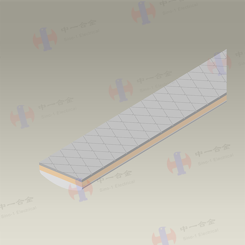
Testing full-width overlays presents unique geometric challenges. Edge-rolling effects often thin out the cladding at the extreme margins of the strip. The rolling mill rolls bend slightly under immense pressure, creating a crown in the center and thinner edges. This thinning increases the likelihood of holidays. When evaluating an overlay clad metal strip, sensors must track the edges carefully. Uniform thickness verification across wide surface areas requires multiple eddy current probes arrayed in a staggered grid to ensure 100% coverage.
Inlays embed a precious metal track into a base metal channel. This creates distinct transition boundaries. Checking continuity here proves difficult. The skiving or rolling process creates a trench, and the corners of this trench act as mechanical stress risers. When testing an inlay clad metal strip, QA teams must focus heavily on these transition zones. Gaps frequently form along the sidewalls of the inlay channel during the final annealing phase due to differing rates of thermal expansion between the base and the inlay metal.
Raised onlays sit proud of the base metal surface. This topography complicates automated inspection. The raised edges act as mechanical stress points. During the rolling process, the onlay material experiences lateral spread. This spread risks micro-cracking along the elevated margins. Inspecting an onlay clad metal strip requires multi-angle AOI cameras. Overhead cameras alone will miss the micro-cracks hiding on the vertical sidewalls of the raised profile. Electrical brushes must be custom-shaped to maintain contact with both the raised profile and the flat base metal simultaneously.
Even the best testing protocols fail if implemented poorly. Engineering teams must anticipate diagnostic errors, environmental variables, and organizational gaps that compromise quality control data.
Electrical testing carries inherent risks of misinterpretation. High ambient factory humidity or surface moisture causes false positives. The water conducts the test voltage across the surface, simulating a pinhole where none exists. Conversely, trapped polishing debris or residual stamping lubricants act as insulators. They fill the pinholes and mask the defects, resulting in dangerous false negatives. Strict environmental controls, HVAC dehumidification, and inline pre-test cleaning stations eliminate these variables.
Organizational gaps in quality control cause massive inefficiencies. You must clearly define the areas of responsibility between the clad metal manufacturer and your incoming inspection team. Process overlaps cause conflict, duplication of effort, and conflicting test interpretations. The vendor should handle 100% inline NDT (eddy current and AOI) and batch destructive testing (SEM). The end-user should perform randomized AQL Level II receiving inspections using DPI or low-voltage electrical checks to verify the vendor's Mill Test Reports.
Continuity defects rarely happen by chance. They usually trace back to improper surface preparation before the metals ever meet. If the base metal oxidizes before the cladding process, the overlay will not bond. Residual rolling oils or airborne dust contaminate the interface. This contamination vaporizes during annealing, creating subsurface gas pockets. These pockets eventually rupture under rolling pressure, forming surface pinholes. Rigorous chemical degreasing, plasma cleaning, and mechanical wire brushing of the substrate prevent these root causes.
Vague contracts lead to poor material quality. Procurement and engineering teams must provide a strict framework for acceptable porosity limits. Define exactly how many pinholes are allowed per linear foot or square meter. Specify the maximum allowable pinhole diameter (e.g., "no pinhole larger than 50 microns"). Mandate specific testing documentation, including comprehensive Mill Test Reports (MTRs) and Certificates of Analysis (CoAs) shipped with every coil. Clearly outline QA liability in vendor contracts to ensure financial protection against batch failures.
Audit your current material specifications to ensure explicit porosity thresholds and maximum defect diameters are defined in writing.
Request detailed porosity testing protocols, equipment calibration records, and recent MTR samples from your current suppliers.
Implement a randomized incoming inspection protocol using low-voltage electrical porosity detectors to verify vendor claims.
Consult with a specialized clad metal engineer to design a custom QA framework for complex inlay or onlay profiles that standard testing misses.
A: Cross-sectional SEM analysis is the most accurate for depth and bond verification, while high-voltage electrical testing using specialized porosity detection instruments is the most effective for full-surface scanning.
A: Results are interpreted by measuring defect density against acceptable ASTM/ISO thresholds. They must be formally documented in Mill Test Reports (MTRs) or Certificates of Analysis (CoAs) to ensure full material traceability.
A: No, dye penetrant inspection relies on capillary action and can only detect surface-breaking pinholes and cracks. It cannot identify hidden delamination or internal voids.
A: Inlays require targeted inspection at the skived transition boundaries where the base metal meets the precious metal, as these are high-stress areas prone to micro-gapping.
A: Root causes include substrate contamination, trapped gases, uneven rolling pressure, or incompatible thermal expansion rates during annealing.
A: Generally, no. Low-voltage tests are completely non-destructive, though improper high-voltage spark testing can cause localized burning if voltage parameters exceed the overlay's dielectric strength.
A: Standard visual inspections cannot identify micro-porosity, subsurface delamination, or holidays that are invisible to the naked eye but large enough to allow corrosive agents to penetrate the base metal. Specialized grazing angle illumination is required at a minimum.