Views: 0 Author: Site Editor Publish Time: 2026-09-04 Origin: Site
Precision stamping, deep drawing, and forming operations require highly predictable material behaviors. This baseline expectation becomes exponentially more complex when working with multi-metal composites. Specifying these materials requires balancing electrical, thermal, or corrosion-resistant properties with mechanical workability. An incorrect layer thickness ratio introduces severe strain gradients. These gradients lead to localized thickness reduction, waviness, edge cracking, or catastrophic delamination during high-volume manufacturing. To prevent costly tooling modifications and high scrap rates, engineering teams must evaluate how specific layer ratios influence the mechanical dynamics of the material. A minor miscalculation in the core-to-cladding ratio can completely alter the neutral axis during bending, throwing off springback predictability. This guide breaks down the technical evaluation of layer thickness ratios, failure mode mitigation, and specification frameworks for optimal formability. You will learn how to align mechanical properties with tooling designs to ensure seamless production runs.
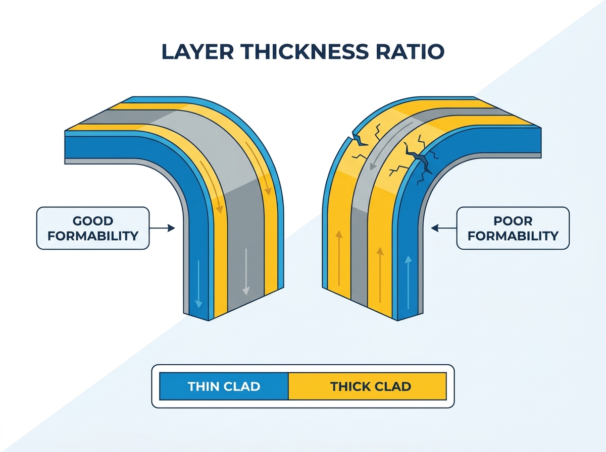
Strain Distribution is Ratio-Dependent: The thickness ratio between dissimilar metals dictates how tensile deformation and strain gradients distribute across the cross-section during forming.
Neutral Axis Shift: In bending operations, mismatched layer thicknesses and yield strengths shift the neutral axis, directly impacting springback predictability and minimum bend radii.
Configuration Matters: The formability constraints for an overlay clad metal strip (full width) differ significantly from an onlay clad metal strip (localized stripe), requiring distinct tooling approaches.
Thermal and Multi-Layer Complexity: Increasing the number of cladding layers (e.g., tri-clads) or introducing uneven cooling rates during processing can result in unpredictable widening and uneven overall forming thickness.
Interface Integrity is Non-Negotiable: Even with an optimal thickness ratio, formability relies entirely on a metallurgical bond free of oxides, grease, or particulate contamination prior to rolling.
Bonding metals with different mechanical properties creates complex strain gradients during cold working. When a punch strikes a composite metal, the distinct layers do not deform at the same rate. The yield strength, tensile strength, and elongation characteristics of each constituent metal dictate the flow of material. If you bond a highly ductile copper layer to a rigid steel core, the applied force distributes unevenly across the cross-section. This unequal distribution generates internal shear stresses at the bond interface.
Tensile deformation in the softer layer generally decreases as the thickness of the harder metal layer increases. The harder layer acts as a rigid backing. It restricts the natural flow of the softer metal. If the harder layer dominates the thickness ratio, it forces the softer layer to conform to its deformation limits. Conversely, if the softer layer is too thick, it may flow excessively. This leaves the harder core unsupported and prone to fracture. The aspect ratio of the layers directly influences the overall ductility of the composite. Engineers must calculate the composite elongation value, which is rarely a simple average of the two materials. It requires analyzing the volume fraction and strain-hardening exponent of each layer to predict how clad metals will behave under tension.
To evaluate strain gradients effectively on the shop floor, follow these steps:
Measure the incoming coil thickness at five distinct points across the width to verify ratio consistency.
Run a tensile test parallel and perpendicular to the rolling direction to check for anisotropy.
Compare the elongation at fracture against the theoretical composite value provided by the metallurgist.
Identify the failure initiation point under magnification to determine which layer fractured first.
The neutral axis represents the theoretical line within a sheet metal cross-section where the material experiences zero stress during bending. Above this axis, the material undergoes tension; below it, the material undergoes compression. In a monolithic metal of uniform thickness, the neutral axis typically sits near the center of the sheet. In a composite material, differing elastic moduli and yield strengths disrupt this symmetry.
A thicker, higher-strength layer pulls the neutral axis toward itself. This shift alters the compression and tension zones significantly. If the neutral axis moves closer to the inner radius, the outer layer experiences a massive increase in tensile strain. This raises the risk of surface fracturing. Tooling engineers must calculate bend allowances based on these ratio-induced axis shifts. Standard K-factor charts for monolithic metals do not apply here. You must evaluate the weighted average of the elastic moduli and adjust the K-factor to account for the dominant layer. Failing to map the shifted neutral axis results in inaccurate blank sizes, inconsistent bend angles, and parts that fail dimensional inspection.
Deep drawing pushes materials to their absolute forming limits. The layer ratio directly impacts the limiting drawing ratio (LDR). LDR defines the maximum blank diameter that can be successfully drawn into a cup without tearing. When drawing multi-metal composites, the sequence and thickness of the layers dictate success or failure. A thick, highly ductile outer layer acts as a buffer. It absorbs the intense compressive forces at the die radius. This prevents the premature fracture of a less ductile core layer.
Extreme ratios introduce specific defects. If the outer layer is too thin to accommodate the draw depth, it stretches beyond its tensile limit. This results in orange peeling or severe surface degradation. The thin layer essentially tears apart microscopically, ruining the surface finish and compromising corrosion resistance. On the other hand, specifying overly thick functional walls increases weight and material costs unnecessarily. Engineers must find the precise ratio threshold where the ductile layer provides enough buffer capacity without dominating the cross-section and inflating the raw material footprint. Adjusting the blank holder force is mandatory when the ratio heavily favors the softer cladding, as excessive pressure will strip the cladding right off the core.
Springback is the elastic recovery of sheet metal after bending. It is notoriously difficult to predict in composites. The ratio of high-yield to low-yield materials complicates springback calculations because each layer wants to recover to a different degree. A high-yield strength layer stores more elastic energy during the bend. If this layer forms the bulk of the composite thickness, the entire strip will exhibit aggressive springback.
Tooling engineers must adjust overbending angles based on the dominant layer's thickness and work-hardening rate. If the ratio favors a soft, low-yield metal, the springback will be minimal. If the ratio favors a rigid, high-yield metal, the die must be cut with a significantly sharper angle to compensate. The challenge arises when ratios are nearly equal, causing competing elastic recoveries that can twist or warp the part upon release from the die. Precise ratio control ensures the dominant layer dictates the springback uniformly, allowing for accurate tooling compensation across high-volume runs.
Rolling and slitting operations expose the vulnerabilities of disproportionate layer thicknesses. Significant strain gradients across the composite lead to waviness and local thickness reduction during hot and cold rolling. When the reduction forces compress the strip, a massive mismatch in layer thickness forces the softer metal to extrude laterally faster than the harder metal. This differential lateral flow creates wavy edges and internal stress pockets.
There are specific threshold ratios where edge cracking becomes a high-probability risk during slitting and subsequent forming. If a hard, brittle layer is too thin relative to a thick, soft core, the shearing action of the slitting blades will micro-fracture the hard layer. These micro-fractures act as stress concentrators. When the slit strip enters a stamping press, those edge cracks propagate rapidly across the width of the part. Maintaining a balanced ratio prevents excessive lateral extrusion and ensures the slitting blades shear the composite cleanly without fracturing the subordinate layer.
Overlay cladding involves applying a secondary metal across 100% of the base metal's surface area, either on one side or both sides. This configuration provides uniform thickness ratios across the entire strip width. The primary formability advantage of an overlay clad metal strip is predictable strain distribution. Because the cross-section remains consistent, the material flows evenly into die cavities, and the neutral axis remains constant along the length of the bend.
Symmetrical overlay ratios, such as a 10/80/10 configuration (10% cladding, 80% core, 10% cladding), offer exceptional stability. The balanced outer layers neutralize competing springback forces, keeping the strip perfectly flat during progressive stamping. Asymmetrical ratios, such as a 10/90 configuration, introduce bowing or curling tendencies. The single clad layer exerts unequal tension on the core after rolling. Tooling engineers must implement specialized flattening stations or utilize roller levelers to counteract the natural coil set induced by asymmetrical overlay ratios before the material feeds into the press.
Onlay cladding places localized stripes of precious or specialty metals onto specific zones of the base metal. This technique conserves expensive materials like silver or gold by placing them only where electrical contact or specific functionality is required. However, an onlay clad metal strip introduces severe formability challenges due to the physical step-down or transition zone between the onlay and the bare base metal.
This transition zone acts as a massive stress concentrator. When forming forces apply tension across the width of the strip, the strain localizes at the boundary where the thickness changes abruptly. If the onlay ratio is too thick relative to the base, the shear stress at the boundary will cause the onlay to peel or the base metal to tear. Tooling mitigation strategies are critical here. Engineers must design dies with localized reliefs to accommodate the extra thickness of the stripe. The pressure pads must hold the base metal firmly without crushing the onlay, preventing shear stress from initiating at the delicate boundary line during the downstroke.
The specific pairing of metals fundamentally alters how the thickness ratio dictates overall forming behavior. Common pairings like copper-clad steel or aluminum-clad stainless steel present distinct engineering challenges. In a copper-clad steel composite, the steel provides structural rigidity while the copper delivers electrical conductivity. The ratio determines which metal governs the press dynamics.
Engineers face a constant trade-off. Maximizing the functional layer versus maximizing the structural layer. If you specify a thicker copper layer to boost ampacity, the overall strength of the part decreases. The material becomes highly susceptible to galling in the die, requiring specialized barrier lubricants to prevent copper buildup on the tooling. Conversely, if you maximize the steel core for structural integrity and leave the copper layer too thin, the functional layer risks mechanical tearing during deep draws. An overly thin functional layer also suffers from poor adhesion. There is simply not enough material mass to sustain the metallurgical bond under extreme deformation, leading to flaking along the bend radii.
Metals work-harden at different rates. When you bond a rapid-hardening metal like stainless steel to a slow-hardening metal like aluminum, the thickness ratio becomes the critical variable in multi-stage progressive die operations. As the composite moves through successive forming stations, the stainless steel layer hardens quickly, requiring exponentially more tonnage to deform. The aluminum layer remains relatively ductile.
Specifying a ratio that heavily favors the rapid-hardening material necessitates intermediate annealing processes. If the hard layer is too thick, it will reach its terminal yield point before the part is fully formed, causing catastrophic cracking. The ductile layer cannot compensate for the sudden loss of plasticity in the dominant layer. To avoid mid-process annealing, engineers must adjust the ratio to ensure the rapid-hardening layer is thin enough to deform alongside the softer core without exceeding its ultimate tensile strength.
Moving from a bi-metal composite to a tri-clad or quad-clad composite introduces compounding variables. Each additional layer adds a new neutral axis shift, a new work-hardening rate, and a new thermal expansion coefficient. Managing the thickness ratios in these multi-layer stacks requires precise metallurgical control. If the core layer is too soft relative to the multiple outer layers, the core will crush under the pressure of the punch, causing the outer layers to buckle inward.
Thermal processing further complicates multi-layer ratios. Uneven cooling methods or thermal dissipation rates during hot rolling and annealing cause severe dimensional instability. With the increase of the number of cladding layers, the cladding layer becomes wider unpredictably, resulting in uneven overall forming thickness. The differing thermal contraction rates create internal residual stresses. If a thick layer cools slower than a thin layer, it warps the strip. Engineers must specify strict cooling protocols to ensure the multi-layer composite remains dimensionally stable and flat prior to stamping.
Delamination is the primary failure mode in composite metal forming. It occurs when layer ratios force excessive shear stress at the metallurgical bond line, tearing the metals apart. If a ratio pairs a massive, rigid core with a paper-thin cladding, the bending forces will concentrate entirely at the interface. The bond line simply cannot withstand the differential strain, and the cladding peels away.
Even with a mathematically perfect thickness ratio, the bond will fail without absolute manufacturing cleanliness. The prerequisite for any composite metal is the complete absence of grease, dust, or oxides prior to the bonding process. If grease or dust gets between the two layers during the initial rolling phase, it creates microscopic voids. These voids act as initiation points for delamination. The metallurgical bond must be pristine to survive the intense strain gradients dictated by the thickness ratio during deep drawing or tight-radius bending.
Necking occurs when a material thins out disproportionately under tension before fracturing. In composite metals, an improper ratio accelerates this failure. If the softer layer is too thick and the harder layer is too thin, the softer layer will begin to neck long before the harder layer reaches its yield point. The harder layer, lacking the structural mass to support the load, will snap immediately after the softer layer begins to thin.
This leads to a complete loss of material integrity. To prevent this, quality control teams must establish strict inspection criteria for identifying localized thinning during prototype runs. Using ultrasonic thickness gauges or cross-sectional micrography, engineers can measure the exact reduction of each individual layer after forming. If the softer layer thins by more than 20% while the harder layer remains unchanged, the ratio must be adjusted to distribute the tensile load more evenly.
Standard monolithic tooling designs will destroy composite metals. You must modify the die architecture to accommodate the unique anisotropic behavior of the specific layer ratio. Implement the following adjustments:
Increase punch radii to prevent slicing through the softer outer layers. If a punch is too sharp, it will penetrate the cladding and expose the core metal.
Recalculate the clearance between the punch and die. The softer layer will drag, and the harder layer will resist. Adjust clearance based on the dominant layer's flow characteristics.
Apply specialized high-pressure barrier lubricants. The lubricant must withstand the high friction generated by the hard layer while protecting the surface finish of the soft layer.
Implement localized reliefs in the die block to accommodate transition zones in striped materials.
Adjust pressure pad force to hold the base metal firmly without crushing the softer cladding.
Before ordering raw material, engineering teams must build a framework for balancing functional requirements against mechanical limits. You must define the minimum acceptable ampacity, thermal transfer rate, or corrosion resistance. These functional metrics dictate the absolute minimum thickness of the functional cladding layer. Once the minimum functional thickness is established, you must evaluate the mechanical limits: minimum bend radius, maximum draw depth, and required yield strength.
Layer Configuration and Formability Impact
Layer Configuration | Primary Formability Risk | Tooling Mitigation Strategy |
|---|---|---|
Thick Hard Core / Thin Soft Clad | Soft clad tearing or extreme surface galling | Increase die radii; utilize high-pressure barrier lubricants. |
Thick Soft Core / Thin Hard Clad | Hard clad micro-fracturing; edge cracking | Optimize slitting blade clearance; implement generous bend radii. |
Symmetrical (e.g., 10/80/10) | Core crushing under high compression | Maintain uniform hold-down pressure; avoid sharp step-downs. |
Asymmetrical (e.g., 10/90) | Severe coil set and twisting post-stamping | Integrate roller levelers before the press; adjust overbend angles. |
Guesswork in composite metal specification leads to catastrophic tooling damage. Advocate heavily for the use of Finite Element Analysis (FEA) to simulate the forming process before finalizing the layer thickness ratio. FEA software can map the exact strain gradients, predict thermal cooling effects, and visualize the neutral axis shifts across the dissimilar metals. By inputting the specific mechanical properties of each layer, engineers can identify necking or delamination risks virtually.
Following FEA, establish a rigorous physical testing protocol for the clad metal strip. Conduct tensile testing to verify the composite yield strength and elongation limits. Utilize the Erichsen cupping test to evaluate the ductility and adhesion of the cladding under multi-axial stretch forming. Physical validation of prototype strips ensures the specified ratio will scale seamlessly into high-volume production without unexpected scrap rates.
Audit your current tooling designs against the specific yield strengths and work-hardening rates of your desired composite ratio.
Recalculate all bend allowances and springback projections based on the shifted neutral axis of the multi-metal cross-section.
Request prototype strips for physical validation, specifically running Erichsen cupping tests and cross-sectional micrography to verify bond integrity.
Inspect prototype runs for localized thinning or necking in the softer layers before scaling to full production.
A: There is no universal ideal ratio. It depends entirely on the ductility of the constituent metals. A thicker ductile outer layer generally improves the limiting drawing ratio (LDR). It acts as a buffer against die friction while preventing the less ductile core from fracturing under severe compressive forces.
A: An overlay strip provides full surface coverage, resulting in uniform strain distribution and consistent neutral axis alignment. An onlay strip features localized stripes. These stripes create severe stress concentrations and shear forces at the physical transition edges during bending or drawing operations.
A: Delamination occurs when extreme strain gradients, improper layer ratios, or excessively tight bend radii generate shear forces that exceed the metallurgical bond strength. Initial bond contamination, such as trapped grease, dust, or oxides prior to rolling, guarantees premature delamination under stress.
A: Yes. Metallurgical data shows that as the thickness of a harder, stronger metal layer increases, the tensile deformation of the softer layer typically decreases. The rigid layer restricts the natural flow of the softer material, forcing it to conform to the harder metal's limits.
A: Springback calculations cannot rely on standard monolithic charts. You must account for the shifted neutral axis. Calculate the weighted average of the differing yield strengths, elastic moduli, and work-hardening rates of the specific layer ratio to determine the correct overbending angle.
A: Yes. Asymmetrical ratios exert unequal tension across the core, causing natural coil set or bowing. Multi-layer configurations can widen unpredictably and develop uneven overall forming thicknesses due to differing thermal expansion and contraction rates during processing.