Views: 0 Author: Site Editor Publish Time: 2026-09-08 Origin: Site
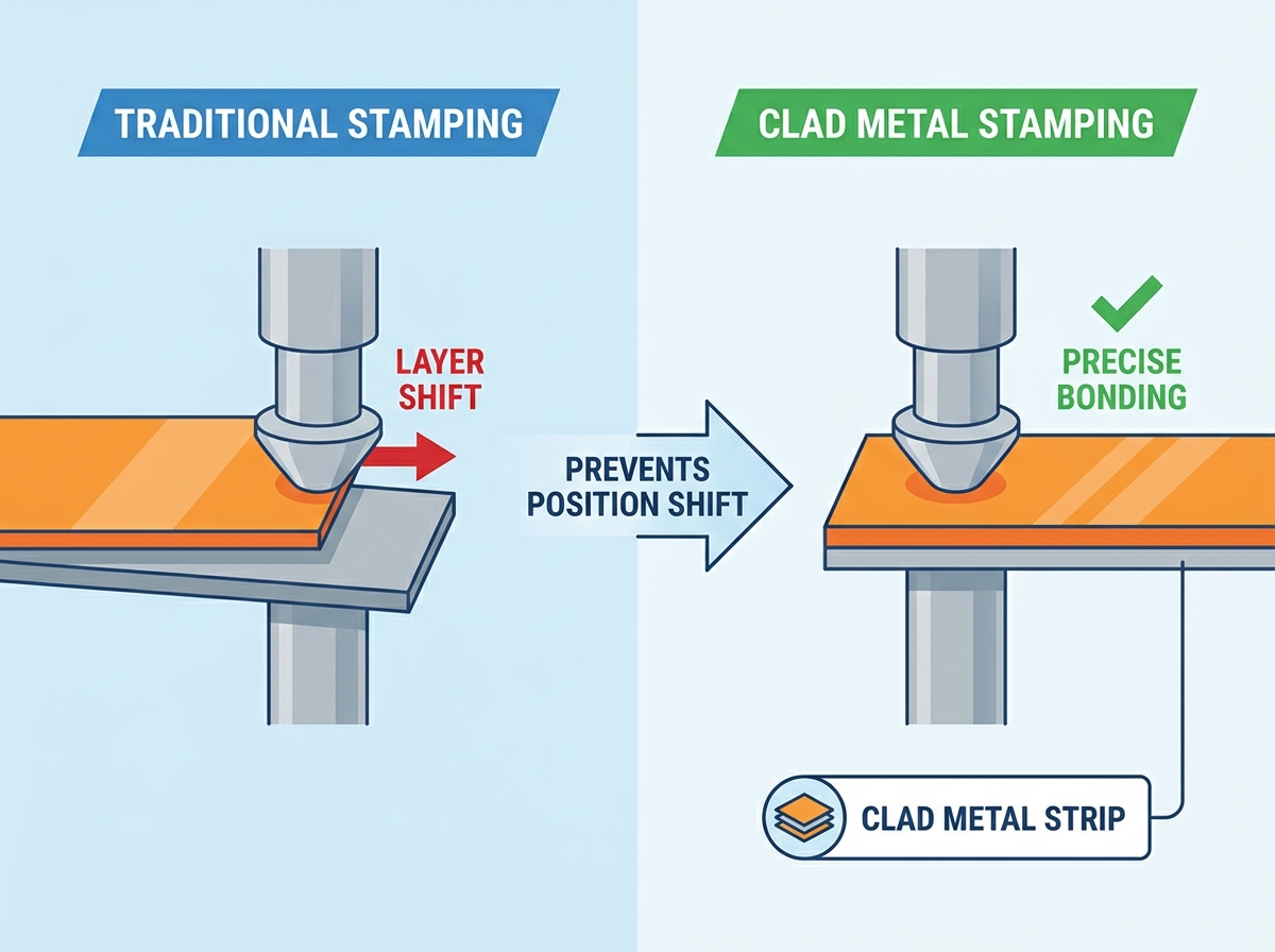
In multi-material manufacturing, shear forces during high-speed stamping represent a severe failure point. Extreme pressures cause layer separation, dimensional inaccuracy, and complete component failure. When layers shift, operational costs multiply through scrapped production runs and catastrophic tooling damage. Traditional mechanical fastening and thick plating fail under high-stress deformation. They cannot withstand the aggressive shear forces inherent in progressive die operations. To eliminate interlayer movement, engineers turn to metallurgically bonded clad metals. This engineering solution ensures absolute dimensional stability during extreme forming operations. Unlike superficial coatings, these bonded materials act as a single monolithic entity. They solve the core problem of layer position shift at the atomic level. We will examine how metallurgical bonding prevents delamination, how to select the right strip profiles, and how to optimize die designs for zero-defect manufacturing.
Metallurgical Bonding Over Mechanical Joining: Clad metals utilize high-pressure roll bonding and thermal treatments to create an atomic-level bond, rendering layer shift physically impossible under standard stamping parameters.
Yield Strength Synchronization: Preventing shift requires matching the temper and formability of the constituent metals to ensure they deform uniformly within the die.
Configuration Dictates Stability: Selecting the correct profile—whether an inlay clad metal strip or an onlay clad metal strip—directly impacts how shear stresses are distributed during the stamping stroke.
Diagnosing layer position shift requires analyzing the physics of metal deformation on the shop floor. During a stamping stroke, the punch applies immense localized pressure to the material blank. This pressure forces the metal to flow into the die cavity. When forming multi-material strips, differential material flow becomes a major obstacle. Each metal possesses a unique yield strength, hardness, and elongation limit. As the punch impacts the composite strip, these differing properties generate severe shear stress at the interface. If the interface lacks structural integrity, the layers slide against each other. Springback discrepancies further exacerbate the issue. Upon release from the die, softer metals spring back less than harder metals. This creates residual internal stresses that tear weak bonds apart. The interaction between the stripper plate, pressure pads, and the material blank must be perfectly balanced. If the clamping force is uneven, the material will draw unevenly, instantly causing the layers to shift out of alignment.
We categorize layer shift into three distinct failure modes observed during production:
Lateral shear shift: Occurs during blanking and piercing operations. The downward force of the punch pushes the top layer sideways relative to the bottom layer. You see smeared edges and out-of-tolerance dimensions on the final part.
Longitudinal elongation mismatch: Happens during deep drawing. The softer layer stretches faster than the harder base layer. The material curls, wrinkles, or tears along the draw radius.
Localized micro-delamination: Presents at tight bend radii. The outer layer undergoes extreme tension while the inner layer faces severe compression. This opposing force fractures weak surface bonds, lifting the top layer away from the base.
Diagnosing the root cause of layer shift demands a systematic approach. Engineers must determine whether the failure stems from material weaknesses or mechanical press issues. Industrial metal stamping faces layer shift primarily due to metallurgical interface failure under immense tonnage. Material failure typically manifests as weak surface adhesion, where plated or bonded layers peel away cleanly. Mechanical press issues present differently. Loose feed mechanisms, die misalignment, or improper tonnage settings cause inconsistent feed lengths. This results in asymmetrical deformation, forcing the layers to absorb uneven shear loads.
Traditional alternatives fail repeatedly under the extreme pressures of progressive die stamping. Electroplating deposits a thin layer of metal onto a substrate, relying purely on mechanical surface adhesion. Under severe bending or drawing, this plated layer flakes, cracks, or spalls off. Adhesive bonding utilizes industrial glues to join metal strips. The heat generated by high-speed stamping friction melts or degrades the adhesive, causing immediate catastrophic delamination. Mechanical staking physically crimps two metals together. Repeated vibration and thermal cycling loosen the staked joints, leading to micro-movements and eventual electrical or structural failure.
A successful multi-metal stamping operation demands strict baseline parameters. The primary success criterion is zero delamination under maximum die pressure. The composite material must exhibit uniform elongation, allowing all layers to stretch and compress simultaneously without separating. The stamped component must maintain strict adherence to geometric tolerances, ensuring consistent springback and precise final dimensions across millions of cycles.
The science of the metallurgical bond provides the foundation for layer stability. Solid-state welding drives this process. Manufacturers pass dissimilar metal strips through massive rolling mills at room temperature. This cold roll bonding applies extreme pressure, often achieving a 50% to 70% reduction in combined thickness in a single pass. The severe deformation shatters brittle surface oxides, exposing virgin metal atoms on both surfaces. Forced into intimate contact under millions of pounds of force, these atoms begin sharing electrons. Subsequent thermal treatment, known as annealing, accelerates atomic diffusion across the boundary. Engineers run the bonded coils through continuous furnaces with controlled atmospheres, typically using hydrogen and nitrogen mixes to prevent oxidation. This creates a true alloy layer at the interface, permanently welding the distinct metals together without melting them.
We must contrast atomic-level adhesion with surface adhesion to understand this stability. Superficial coatings, like electroplating or physical vapor deposition, sit on top of the base metal. They rely on microscopic surface roughness to hold on. When the base metal bends, the coating cannot stretch at the same rate and breaks away. Metallurgically bonded materials act as a single monolithic entity. The electron sharing creates a permanent structural integration. You cannot peel the layers apart, even under extreme mechanical destruction. The composite material behaves as one unified metal during all phases of deformation.
Managing differential yield strengths requires precise metallurgical engineering. You cannot simply roll two random metals together and expect them to stamp well. Metallurgists must balance the mechanical properties of the base metal and the cladding. They adjust rolling reduction ratios and annealing temperatures to ensure both metals reach a compatible temper. If a hard steel base pairs with a soft gold cladding, the gold will smear during blanking. By work-hardening the gold and fully annealing the steel, engineers synchronize their yield strengths. This ensures both materials flow together seamlessly without shearing at the interface.
Inlay cladding features a specific profile where the precious or specialty metal embeds flush with the base material. Manufacturers mill a precise groove into the base metal, insert the secondary metal wire or strip, and roll-bond them together. The resulting composite strip maintains a perfectly flat, uniform surface across its entire width.
This flush profile provides exceptional shift prevention mechanics. Because the clad layer sits level with the base metal, the stamping die impacts a flat surface. The flush design protects the clad layer from direct lateral die impact. It minimizes edge-shear risks during aggressive blanking and coining operations. The die does not catch the edge of the precious metal, eliminating the primary catalyst for lateral layer shift.
Engineers specify an inlay clad metal strip for high-reliability electrical contacts and connectors. These components require precise localized conductivity without dimensional variance. The flush profile allows progressive dies to feed the material smoothly, ensuring exact placement of the contact material on every single stamped part.
Onlay cladding presents a profile where the secondary metal sits proud, or raised, on the surface of the base metal. The bonding process attaches a narrower strip of specialty metal onto the flat surface of a wider base strip. This creates a distinct topographical step along the length of the coil.
Managing shear stress with this raised profile demands specific die design requirements. Standard flat dies will crush the raised onlay, causing severe lateral shift and material smearing. Tooling engineers must design precise clearances and reliefs into the die face. These pockets accommodate the raised profile, preventing the tool steel from inducing lateral shift or scraping the onlay during the downward stamping stroke. Proper radii on the die relief edges prevent stress concentrations that could initiate micro-cracking.
An onlay clad metal strip excels in applications requiring wear surfaces, thermal management components, and electromechanical switches. In these designs, a raised contact point is mandatory to ensure proper mechanical engagement or electrical arcing clearance. The raised profile concentrates contact force exactly where the design requires it.
Full-overlay materials feature edge-to-edge bonding of two or more distinct metal layers. The composite strip maintains a uniform thickness across its entire width and length, resembling a standard single-alloy coil. This configuration often combines a highly conductive core with corrosion-resistant outer layers.
This uniform thickness provides significant formability advantages. It simplifies die clearance calculations, as engineers treat the material as a single sheet rather than a stepped profile. Full-overlay materials offer the highest resistance to layer shift during deep drawing operations. The uniform distribution of clamping force from the blank holder ensures even material flow into the die cavity, preventing longitudinal elongation mismatch and wrinkling.
Calculating die clearances requires a specialized engineering framework when working with composite materials. You cannot base punch-to-die clearance solely on the properties of the base metal. Engineers must calculate clearance based on the composite shear strength of the bonded strip. If you use clearance formulas designed for pure copper on a copper-clad steel strip, the steel core will fracture prematurely, leaving jagged edges and inducing layer shift. A weighted average based on layer thickness and individual shear strengths provides the optimal clearance parameter.
Designing proper radii and bend allowances prevents failure at the most vulnerable points of the stamped component. Tight bend radii force the outer layer into extreme tension and the inner layer into severe compression. To prevent tension-side cracking of the clad layer, the bend radius must exceed the minimum bend radius of the least ductile metal in the composite. Conversely, to prevent compression-side wrinkling, engineers must control the material flow using precise pressure pads within the die.
Lubrication prevents catastrophic tool wear and material galling. Softer clad layers, such as gold, silver, or pure copper, tend to cold-weld to hardened tool steel under extreme pressure. This galling builds up on the die face, eventually gouging the strip and forcing layer shift. Tooling engineers often specify premium tool steels like M2 or tungsten carbide, coated with Titanium Nitride (TiN) or Diamond-Like Carbon (DLC), to reduce friction. Specialized stamping lubricants, formulated with extreme pressure additives, create a chemical barrier between the strip and the tool. This ensures smooth material flow and protects the delicate clad surface.
Machine-level shift prevention remains mandatory, even with perfectly bonded materials. Rigid press alignment ensures the punch enters the die cavity perfectly parallel. Any angular deflection during the stroke introduces asymmetrical shear forces, which can initiate localized delamination. Facilities utilize dynamic parallelism checks and tonnage monitors to detect off-center loading in real-time. Precise servo-feed calibration guarantees the strip advances the exact required distance for each stroke. Misfeeds cause the die to strike the material off-center, generating lateral forces that compromise the integrity of clad metal stamping parts. Pilot pins must be perfectly sized to locate the strip without distorting the pilot holes. Routine die inspection identifies worn punches, galled surfaces, and degraded springs before they cause catastrophic material failure.
Intermediate annealing during the cladding process dictates the final formability of the strip. Cold roll bonding work-hardens the metals significantly, making them brittle and prone to cracking. Passing the bonded strip through controlled atmosphere furnaces relieves these internal stresses. Metallurgists carefully control the time and temperature to ensure both metals reach a compatible temper for stamping. This ensures they yield and flow simultaneously under the press.
Grain structure alignment directly prevents micro-tearing. The rolling process elongates the metal grains in the direction of rolling. Bending the material parallel to this grain direction increases the risk of cracking and subsequent layer shift. Tooling engineers must orient the blanking layout so critical bends occur perpendicular, or transverse, to the rolling direction. This maximizes the ductility of the composite and maintains bond integrity during extreme deformation.
While the metallurgical bond operates at the atomic level, improper stamping parameters can still induce failure. Exceeding the composite's elongation limit during excessive deep drawing will cause the least ductile layer to fracture. This micro-cracking compromises the structural integrity of the component and can propagate into localized delamination along the edges.
Mitigating these risks requires rigorous non-destructive testing prior to full-scale production. Ultrasonic inspection scans the bonded coil for microscopic voids or unbonded regions before it ever reaches the press. Bend testing subjects sample strips to extreme deformation, verifying that the bond remains intact well beyond the intended design limits. These verification steps ensure only flawless material enters the progressive die.
Blanking a composite strip exposes the cross-section of dissimilar metals along the cut edge. In the presence of an electrolyte, such as ambient humidity or industrial fluids, this exposed edge creates a potential galvanic couple. The more anodic metal will corrode rapidly, degrading the edge quality and potentially undercutting the bond interface over years of field service.
Engineers mitigate this risk through careful material selection and post-stamping treatments. Specifying compatible metal pairings with similar anodic indices minimizes the galvanic potential. When highly dissimilar metals are mandatory, post-stamping treatments become necessary. Applying environmental sealing, conformal coatings, or localized edge plating neutralizes the corrosion risk, ensuring the stamped component survives its intended operating environment.
Unlike other manufacturing processes where shifted layers might be salvaged, delaminated stamped parts represent immediate, unrecoverable scrap. You cannot re-weld or press a shifted clad layer back into position. The dimensional tolerances are permanently destroyed, and the atomic bond is irreparably broken. This scrap reality reinforces the absolute necessity of utilizing preventative metallurgical bonding upfront, rather than relying on inferior joining methods that risk catastrophic failure during the stamping stroke.
Configuration Comparison Matrix
Configuration Type | Profile Characteristic | Primary Shear Protection | Ideal Application |
|---|---|---|---|
Inlay | Flush embedded surface | Protects from lateral die impact | Precision electrical contacts |
Onlay | Raised topographical step | Requires specific die relief | Wear surfaces and switches |
Full-Overlay | Edge-to-edge uniform thickness | Simplifies clearance calculations | Deep-drawn structural components |
Evaluating the financial viability of composite materials requires looking beyond the initial purchase order. Upfront material costs for bonded coils are undeniably higher than standard single-alloy strips. However, this initial investment drives massive processing savings downstream. Utilizing pre-bonded coils completely eliminates secondary manufacturing steps. You remove the entire plating line, eliminate the welding station, and discard the riveting process. This consolidation streamlines the supply chain and drastically reduces work-in-progress inventory.
Scrap reduction provides the most significant return on investment. Traditional plated or mechanically fastened components suffer from high defect rates due to flaking, peeling, and layer shift during aggressive forming. By eliminating layer-shift defects entirely, bonded materials push scrap rates toward zero. The absence of flaking plating reduces tool wear, significantly reducing tooling maintenance downtime and extending the life of expensive carbide punches.
Scalability dictates the economic viability of custom composite solutions. For low-volume prototyping, standard off-the-shelf alloys might suffice. As production scales into the millions of units, the volume thresholds easily justify the transition. The elimination of secondary operations and the drastic reduction in scrap make custom bonded strips highly cost-effective for high-volume OEM production.
Engage a metallurgical engineer during the initial prototyping phase to define the exact operational stresses your component will face.
Specify precise alloy pairings and temper requirements to ensure synchronized yield strengths before ordering sample coils.
Design custom strip profiles that align with your specific contact points to minimize precious metal usage.
Finalize die designs, including clearances and reliefs, only after confirming the composite shear strength of the selected material.
A: Layer position shift occurs when extreme shear forces from the stamping punch overcome the bond strength between dissimilar metals. Differences in yield strength, hardness, and springback cause the layers to flow at different rates. If the layers rely on weak surface adhesion, this differential flow tears the interface apart.
A: Material failure typically shows clean peeling or flaking, indicating weak surface adhesion. Press-induced shift presents as asymmetrical deformation, smeared edges, or inconsistent part lengths. Check your servo-feed calibration and die alignment. If the press mechanics are perfect but the layers still separate, the material bond is failing.
A: Electroplating deposits a thin layer that relies purely on mechanical surface adhesion, which easily flakes off under severe bending. Clad materials use extreme pressure and heat to force electron sharing between the metals. This creates a permanent, atomic-level metallurgical bond that acts as a single monolithic entity during deformation.
A: While the atomic bond is incredibly strong, exceeding the composite's maximum elongation limit can induce micro-cracking. However, true delamination is exceptionally rare. The flush profile of an inlay protects the edges from direct die impact, making it highly resistant to shear forces during deep drawing operations.
A: You cannot calculate die clearance based solely on the base metal. You must calculate a weighted average based on the composite shear strength of all bonded layers. Using standard clearances for the harder base metal may cause the softer clad layer to smear, gall, or fracture prematurely.
A: Metallurgists match yield strengths by carefully controlling the rolling reduction ratios and intermediate annealing temperatures during the bonding process. By work-hardening the softer metal and fully annealing the harder base metal, they synchronize their mechanical properties so both layers deform uniformly within the die.